3
Memory Access and Organization

Chapters 1 and 2 showed you how to declare and access simple variables in an assembly language program. This chapter fully explains x86-64 memory access. In this chapter, you will learn how to efficiently organize your variable declarations to speed up access to their data. You’ll also learn about the x86-64 stack and how to manipulate data on it.
This chapter discusses several important concepts, including the following:
- Memory organization
- Memory allocation by program
- x86-64 memory addressing modes
- Indirect and scaled-indexed addressing modes
- Data type coercion
- The x86-64 stack
This chapter will teach to you make efficient use of your computer’s memory resources.
3.1 Runtime Memory Organization
A running program uses memory in many ways, depending on the data’s type. Here are some common data classifications you’ll find in an assembly language program:
Code
- Memory values that encode machine instructions.
Uninitialized static data
- An area in memory that the program sets aside for uninitialized variables that exist the whole time the program runs; Windows will initialize this storage area to 0s when it loads the program into memory.
Initialized static data
- A section of memory that also exists the whole time the program runs. However, Windows loads values for all the variables appearing in this section from the program’s executable file so they have an initial value when the program first begins execution.
Read-only data
- Similar to initialized static data insofar as Windows loads initial data for this section of memory from the executable file. However, this section of memory is marked read-only to prevent inadvertent modification of the data. Programs typically store constants and other unchanging data in this section of memory (by the way, note that the code section is also marked read-only by the operating system).
Heap
- This special section of memory is designated to hold dynamically allocated storage. Functions such as C’s
malloc()andfree()are responsible for allocating and deallocating storage in the heap area. “Pointer Variables and Dynamic Memory Allocation” in Chapter 4 discusses dynamic storage allocation in greater detail.
Stack
- In this special section in memory, the program maintains local variables for procedures and functions, program state information, and other transient data. See “The Stack Segment and the push and pop Instructions” on page 134 for more information about the stack section.
These are the typical sections you will find in common programs (assembly language or otherwise). Smaller programs won’t use all of these sections (code, stack, and data sections are a good minimum number). Complex programs may create additional sections in memory for their own purposes. Some programs may combine several of these sections together. For example, many programs will combine the code and read-only sections into the same section in memory (as the data in both sections gets marked as read-only). Some programs combine the uninitialized and initialized data sections together (initializing the uninitialized variables to 0). Combining sections is generally handled by the linker program. See the Microsoft linker documentation for more details on combining sections.1
Windows tends to put different types of data into different sections (or segments) of memory. Although it is possible to reconfigure memory as you choose by running the linker and specifying various parameters, by default Windows loads a MASM program into memory by using an organization similar to that in Figure 3-1.2
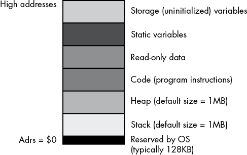
Figure 3-1: MASM typical runtime memory organization
Windows reserves the lowest memory addresses. Generally, your application cannot access data (or execute instructions) at these low addresses. One reason the operating system reserves this space is to help trap NULL pointer references: if you attempt to access memory location 0 (NULL), the operating system will generate a general protection fault (also known as a segmentation fault), meaning you’ve accessed a memory location that doesn’t contain valid data.
The remaining six areas in the memory map hold different types of data associated with your program. These sections of memory include the stack section, the heap section, the .code section, the .data (static) section, the .const section, and the .data? (storage) section. Each corresponds to a type of data you can create in your MASM programs. The .code, .data, .const, and .data? sections are described next in detail.3
3.1.1 The .code Section
The .code section contains the machine instructions that appear in a MASM program. MASM translates each machine instruction you write into a sequence of one or more byte values. The CPU interprets these byte values as machine instructions during program execution.
By default, when MASM links your program, it tells the system that your program can execute instructions and read data from the code segment but cannot write data to the code segment. The operating system will generate a general protection fault if you attempt to store any data into the code segment.
3.1.2 The .data Section
The .data section is where you will typically put your variables. In addition to declaring static variables, you can also embed lists of data into the .data declaration section. You use the same technique to embed data into your .data section that you use to embed data into the .code section: you use the byte, word, dword, qword, and so on, directives. Consider the following example:
    .data
b   byte    0
    byte    1,2,3

u   dword   1
    dword   5,2,10;

c   byte   ?
    byte   'a', 'b', 'c', 'd', 'e', 'f';

bn  byte   ?
    byte   true  ; Assumes true is defined as "1"
Values that MASM places in the .data memory segment by using these directives are written to the segment after the preceding variables. For example, the byte values 1, 2, and 3 are emitted to the .data section after b’s 0 byte. Because there aren’t any labels associated with these values, you do not have direct access to them in your program. You can use the indexed addressing modes to access these extra values.
In the preceding examples, note that the c and bn variables do not have an (explicit) initial value. However, if you don’t provide an initial value, MASM will initialize the variables in the .data section to 0, so MASM assigns the NULL character (ASCII code 0) to c as its initial value. Likewise, MASM assigns false as the initial value for bn (assuming false is defined as 0). Variable declarations in the .data section always consume memory, even if you haven’t assigned them an initial value.
3.1.3 The .const Section
The .const data section holds constants, tables, and other data that your program cannot change during execution. You create read-only objects by declaring them in the .const declaration section. The .const section is similar to the .data section, with three differences:
- The
.constsection begins with the reserved word.constrather than.data. - All declarations in the
.constsection have an initializer. - The system does not allow you to write data to variables in a
.constobject while the program is running.
Here’s an example:
        .const
pi      real4     3.14159
e       real4     2.71
MaxU16  word      65535
MaxI16  sword     32767
All .const object declarations must have an initializer because you cannot initialize the value under program control. For many purposes, you can treat .const objects as literal constants. However, because they are actually memory objects, they behave like (read-only) .data objects. You cannot use a .const object anywhere a literal constant is allowed; for example, you cannot use them as displacements in addressing modes (see “The x86-64 Addressing Modes” on page 122), and you cannot use them in constant expressions. In practice, you can use them anywhere that reading a .data variable is legal.
As with the .data section, you may embed data values in the .const section by using the byte, word, dword, and so on, data declarations, though all declarations must be initialized. For example:
        .const
roArray byte     0
        byte     1, 2, 3, 4, 5
qwVal   qword    1
        qword    0
Note that you can also declare constant values in the .code section. Data values you declare in this section are also read-only objects, as Windows write-protects the .code section. If you do place constant declarations in the .code section, you should take care to place them in a location that the program will not attempt to execute as code (such as after a jmp or ret instruction). Unless you’re manually encoding x86 machine instructions using data declarations (which would be rare, and done only by expert programmers), you don’t want your program to attempt to execute data as machine instructions; the result is usually undefined.4
3.1.4 The .data? Section
The .const section requires that you initialize all objects you declare. The .data section lets you optionally initialize objects (or leave them uninitialized, in which case they have the default initial value of 0). The .data? section lets you declare variables that are always uninitialized when the program begins running. The .data? section begins with the .data? reserved word and contains variable declarations without initializers. Here is an example:
            .data?
UninitUns32 dword  ?
i           sdword ?
character   byte   ?
b           byte   ?
Windows will initialize all .data? objects to 0 when it loads your program into memory. However, it’s probably not a good idea to depend on this implicit initialization. If you need an object initialized with 0, declare it in a .data section and explicitly set it to 0.
Variables you declare in the .data? section may consume less disk space in the executable file for the program. This is because MASM writes out initial values for .const and .data objects to the executable file, but it may use a compact representation for uninitialized variables you declare in the .data? section; note, however, that this behavior is dependent on the OS version and object-module format.
3.1.5 Organization of Declaration Sections Within Your Programs
The .data, .const, .data?, and .code sections may appear zero or more times in your program. The declaration sections may appear in any order, as the following example demonstrates:
           .data
i_static   sdword    0

           .data?
i_uninit   sdword    ?

           .const
i_readonly dword     5

           .data
j          dword     ?

           .const
i2         dword     9

           .data?
c          byte      ?

           .data?
d          dword     ?

           .code

      Code goes here

            end
The sections may appear in an arbitrary order, and a given declaration section may appear more than once in your program. As noted previously, when multiple declaration sections of the same type (for example, the three .data? sections in the preceding example) appear in a declaration section of your program, MASM combines them into a single group (in any order it pleases).
3.1.6 Memory Access and 4K Memory Management Unit Pages
The x86-64’s memory management unit (MMU) divides memory into blocks known as pages.5 The operating system is responsible for managing pages in memory, so application programs don’t typically worry about page organization. However, you should be aware of a couple of issues when working with pages in memory: specifically, whether the CPU even allows access to a given memory location and whether it is read/write or read-only (write-protected).
Each program section appears in memory in contiguous MMU pages. That is, the .const section begins at offset 0 in an MMU page and sequentially consumes pages in memory for all the data appearing in that section. The next section in memory (perhaps .data) begins at offset 0 in the next MMU page following the last page of the previous section. If that previous section (for example, .const) did not consume an integral multiple of 4096 bytes, padding space will be present between the end of that section’s data to the end of its last page (to guarantee that the next section begins on an MMU page boundary).
Each new section starts in its own MMU page because the MMU controls access to memory by using page granularity. For example, the MMU controls whether a page in memory is readable/writable or read-only. For .const sections, you want the memory to be read-only. For the .data section, you want to allow reads and writes. Because the MMU can enforce these attributes only on a page-by-page basis, you cannot have .data section information in the same MMU page as a .const section.
Normally, all of this is completely transparent to your code. Data you declare in a .data (or .data?) section is readable and writable, and data in a .const section (and .code section) is read-only (.code sections are also executable). Beyond placing data in a particular section, you don’t have to worry too much about the page attributes.
You do have to worry about MMU page organization in memory in one situation. Sometimes it is convenient to access (read) data beyond the end of a data structure in memory (for legitimate reasons—see Chapter 11 on SIMD instructions and Chapter 14 on string instructions). However, if that data structure is aligned with the end of an MMU page, accessing the next page in memory could be problematic. Some pages in memory are inaccessible; the MMU does not allow reading, writing, or execution to occur on that page.
Attempting to do so will generate an x86-64 general protection (segmentation) fault and abort the normal execution of your program.6 If you have a data access that crosses a page boundary, and the next page in memory is inaccessible, this will crash your program. For example, consider a word access to a byte object at the very end of an MMU page, as shown in Figure 3-2.
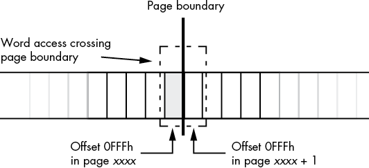
Figure 3-2: Word access at the end of an MMU page
As a general rule, you should never read data beyond the end of a data structure.7 If for some reason you need to do so, you should ensure that it is legal to access the next page in memory (alas, there is no instruction on modern x86-64 CPUs to allow this; the only way to be sure that access is legal is to make sure there is valid data after the data structure you are accessing).
3.2 How MASM Allocates Memory for Variables
MASM associates a current location counter with each of the four declaration sections (.code, .data, .const, and .data?). These location counters initially contain 0, and whenever you declare a variable in one of these sections (or write code in a code section), MASM associates the current value of that section’s location counter with the variable; MASM also bumps up the value of that location counter by the size of the object you’re declaring. As an example, assume that the following is the only .data declaration section in a program:
    .data
b   byte   ?        ; Location counter = 0,  size = 1
w   word   ?        ; Location counter = 1,  size = 2
d   dword  ?        ; Location counter = 3,  size = 4
q   qword  ?        ; Location counter = 7,  size = 8
o   oword  ?        ; Location counter = 15, size = 16
                    ; Location counter is now 31
As you can see, the variable declarations appearing in a (single) .data section have contiguous offsets (location counter values) into the .data section. Given the preceding declaration, w will immediately follow b in memory, d will immediately follow w in memory, q will immediately follow d, and so on. These offsets aren’t the actual runtime address of the variables. At runtime, the system loads each section to a (base) address in memory. The linker and Windows add the base address of the memory section to each of these location counter values (which we call displacements, or offsets) to produce the actual memory address of the variables.
Keep in mind that you may link other modules with your program (for example, from the C Standard Library) or even additional .data sections in the same source file, and the linker has to merge the .data sections together. Each section has its own location counter that also starts from zero when allocating storage for the variables in the section. Hence, the offset of an individual variable may have little bearing on its final memory address.
Remember that MASM allocates memory objects you declare in .const, .data, and .data? sections in completely different regions of memory. Therefore, you cannot assume that the following three memory objects appear in adjacent memory locations (indeed, they probably will not):
    .data
b   byte   ?

    .const
w   word    1234h

    .data?
d   dword   ?
In fact, MASM will not even guarantee that variables you declare in separate .data (or whatever) sections are adjacent in memory, even if there is nothing between the declarations in your code. For example, you cannot assume that b, w, and d are in adjacent memory locations in the following declarations, nor can you assume that they won’t be adjacent in memory:
    .data
b   byte   ?

    .data
w   word   1234h

    .data
d   dword  ?
If your code requires these variables to consume adjacent memory locations, you must declare them in the same .data section.
3.3 The Label Declaration
The label declaration lets you declare variables in a section (.code, .data, .const, and .data?) without allocating memory for the variable. The label directive tells MASM to assign the current address in a declaration section to a variable but not to allocate any storage for the object. That variable shares the same memory address as the next object appearing in the variable declaration section. Here is the syntax for the label declaration:
variable_name label typeThe following code sequence provides an example of using the label declaration in the .const section:
        .const
abcd    label   dword
        byte 'a', 'b', 'c', 'd'
In this example, abcd is a double word whose LO byte contains 97 (the ASCII code for a), byte 1 contains 98 (b), byte 2 contains 99 (c), and the HO byte contains 100 (d). MASM does not reserve storage for the abcd variable, so MASM associates the following 4 bytes in memory (allocated by the byte directive) with abcd.
3.4 Little-Endian and Big-Endian Data Organization
Back in “The Memory Subsystem” in Chapter 1, this book pointed out that the x86-64 stores multi-byte data types in memory with the LO byte at the lowest address in memory and the HO byte at the highest address in memory (see Figure 1-5 in Chapter 1). This type of data organization in memory is known as little endian. Little-endian data organization (in which the LO byte comes first and the HO byte comes last) is a common memory organization shared by many modern CPUs. It is not, however, the only possible data organization.
The big-endian data organization reverses the order of the bytes in memory. The HO byte of the data structure appears first (in the lowest memory address), and the LO byte appears in the highest memory address. Tables 3-1, 3-2, and 3-3 describe the memory organization for words, double words, and quad words, respectively.
Table 3-1: Word Object Little- and Big-Endian Data Organizations
| Data byte | Memory organization for little endian | Memory organization for big endian |
| 0 (LO byte) | base + 0 | base + 1 |
| 1 (HO byte) | base + 1 | base + 0 |
Table 3-2: Double-Word Object Little- and Big-Endian Data Organizations
| Data byte | Memory organization for little endian | Memory organization for big endian |
| 0 (LO byte) | base + 0 | base + 3 |
| 1 | base + 1 | base + 2 |
| 2 | base + 2 | base + 1 |
| 3 (HO byte) | base + 3 | base + 0 |
Table 3-3: Quad-Word Object Little- and Big-Endian Data Organizations
| Data byte | Memory organization for little endian | Memory organization for big endian |
| 0 (LO byte) | base + 0 | base + 7 |
| 1 | base + 1 | base + 6 |
| 2 | base + 2 | base + 5 |
| 3 | base + 3 | base + 4 |
| 4 | base + 4 | base + 3 |
| 5 | base + 5 | base + 2 |
| 6 | base + 6 | base + 1 |
| 7 (HO byte) | base + 7 | base + 0 |
Normally, you wouldn’t be too concerned with big-endian memory organization on an x86-64 CPU. However, on occasion you may need to deal with data produced by a different CPU (or by a protocol, such as TCP/IP, that uses big-endian organization as its canonical integer format). If you were to load a big-endian value in memory into a CPU register, your calculations would be incorrect.
If you have a 16-bit big-endian value in memory and you load it into a 16-bit register, it will have its bytes swapped. For 16-bit values, you can correct this issue by using the xchg instruction. It has the syntax
xchg reg, reg
xchg reg, mem
where reg is any 8-, 16-, 32-, or 64-bit general-purpose register, and mem is any appropriate memory location. The reg operands in the first instruction, or the reg and mem operands in the second instruction, must both be the same size.
Though you can use the xchg instruction to exchange the values between any two arbitrary (like-sized) registers, or a register and a memory location, it is also useful for converting between (16-bit) little- and big-endian formats. For example, if AX contains a big-endian value that you would like to convert to little-endian form prior to some calculations, you can use the following instruction to swap the bytes in the AX register to convert the value to little-endian form:
xchg al, ahYou can use the xchg instruction to convert between little- and big-endian form for any of the 16-bit registers AX, BX, CX, and DX by using the low/high register designations (AL/AH, BL/BH, CL/CH, and DL/DH).
Unfortunately, the xchg trick doesn’t work for registers other than AX, BX, CX, and DX. To handle larger values, Intel introduced the bswap (byte swap) instruction. As its name suggests, this instruction swaps the bytes in a 32- or 64-bit register. It swaps the HO and LO bytes, and the (HO – 1) and (LO + 1) bytes (plus all the other bytes, in opposing pairs, for 64-bit registers). The bswap instruction works for all general-purpose 32-bit and 64-bit registers.
3.5 Memory Access
As you saw in “The Memory Subsystem” in Chapter 1, the x86-64 CPU fetches data from memory on the data bus. In an idealized CPU, the data bus is the size of the standard integer registers on the CPU; therefore, you would expect the x86-64 CPUs to have a 64-bit data bus. In practice, modern CPUs often make the physical data bus connection to main memory much larger in order to improve system performance. The bus brings in large chunks of data from memory in a single operation and places that data in the CPU’s cache, which acts as a buffer between the CPU and physical memory.
From the CPU’s point of view, the cache is memory. Therefore, when the remainder of this section discusses memory, it’s generally talking about data sitting in the cache. As the system transparently maps memory accesses into the cache, we can discuss memory as though the cache were not present and discuss the advantages of the cache as necessary.
On early x86 processors, memory was arranged as an array of bytes (8-bit machines such as the 8088), words (16-bit machines such as the 8086 and 80286), or double words (on 32-bit machines such as the 80386). On a 16-bit machine, the LO bit of the address did not physically appear on the address bus. So the addresses 126 and 127 put the same bit pattern on the address bus (126, with an implicit 0 in bit position 0), as shown in Figure 3-3.8
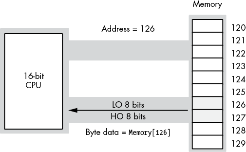
Figure 3-3: Address and data bus for 16-bit processors
When reading a byte, the CPU uses the LO bit of the address to select the LO byte or HO byte on the data bus. Figure 3-4 shows the process when accessing a byte at an even address (126 in this figure). Figure 3-5 shows the same operation when reading a byte from an odd address (127 in this figure). Note that in both Figures 3-4 and 3-5, the address appearing on the address bus is 126.
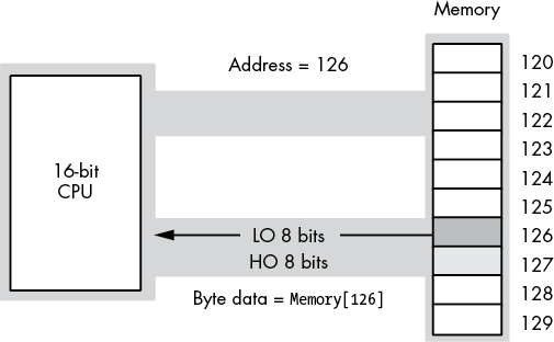
Figure 3-4: Reading a byte from an even address on a 16-bit CPU
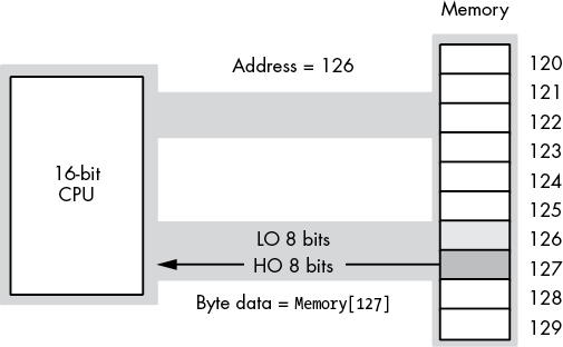
Figure 3-5: Reading a byte from an odd address on a 16-bit CPU
So, what happens when this 16-bit CPU wants to access 16 bits of data at an odd address? For example, suppose in these figures the CPU reads the word at address 125. When the CPU puts address 125 on the address bus, the LO bit doesn’t physically appear. Therefore, the actual address on the bus is 124. If the CPU were to read the LO 8 bits off the data bus at this point, it would get the data at address 124, not address 125.
Fortunately, the CPU is smart enough to figure out what is going on here, and extracts the data from the HO 8 bits on the address bus and uses this as the LO 8 bits of the data operand. However, the HO 8 bits that the CPU needs are not found on the data bus. The CPU has to initiate a second read operation, placing address 126 on the address bus, to get the HO 8 bits (which will be sitting in the LO 8 bits of the data bus, but the CPU can figure that out). The bottom line is that it takes two memory cycles for this read operation to complete. Therefore, the instruction reading the data from memory will take longer to execute than had the data been read from an address that was an integral multiple of two.
The same problem exists on 32-bit processors, except the 32-bit data bus allows the CPU to read 4 bytes at a time. Reading a 32-bit value at an address that is not an integral multiple of four incurs the same performance penalty. Note, however, that accessing a 16-bit operand at an odd address doesn’t always guarantee an extra memory cycle—only addresses whose remainder when divided by four is 3 incur the penalty. In particular, if you access a 16-bit value (on a 32-bit bus) at an address where the LO 2 bits contain 01b, the CPU can read the word in a single memory cycle, as shown in Figure 3-6.
Modern x86-64 CPUs, with cache systems, have largely eliminated this problem. As long as the data (1, 2, 4, 8, or 10 bytes in size) is fully within a cache line, there is no memory cycle penalty for an unaligned access. If the access does cross a cache line boundary, the CPU will run a bit slower while it executes two memory operations to get (or store) the data.
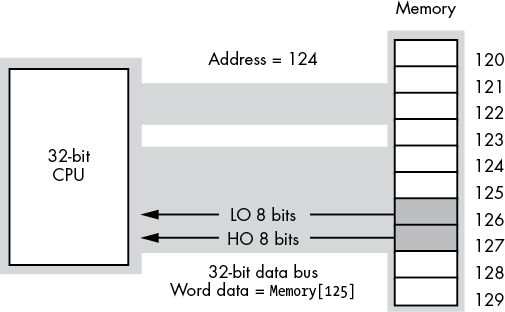
Figure 3-6: Accessing a word on a 32-bit data bus
3.6 MASM Support for Data Alignment
To write fast programs, you need to ensure that you properly align data objects in memory. Proper alignment means that the starting address for an object is a multiple of a certain size, usually the size of an object if the object’s size is a power of 2 for values up to 32 bytes in length. For objects greater than 32 bytes, aligning the object on an 8-, 16-, or 32-byte address boundary is probably sufficient. For objects fewer than 16 bytes, aligning the object at an address that is the next power of 2 greater than the object’s size is usually fine. Accessing data that is not aligned at an appropriate address may require extra time (as noted in the previous section); so, if you want to ensure that your program runs as rapidly as possible, you should try to align data objects according to their size.
Data becomes misaligned whenever you allocate storage for different-sized objects in adjacent memory locations. For example, if you declare a byte variable, it will consume 1 byte of storage, and the next variable you declare in that declaration section will have the address of that byte object plus 1. If the byte variable’s address happens to be an even address, the variable following that byte will start at an odd address. If that following variable is a word or double-word object, its starting address will not be optimal. In this section, we’ll explore ways to ensure that a variable is aligned at an appropriate starting address based on that object’s size.
Consider the following MASM variable declarations:
    .data
dw  dword  ?
b   byte   ?
w   word   ?
dw2 dword  ?
w2  word   ?
b2  byte   ?
dw3 dword  ?
The first .data declaration in a program (running under Windows) places its variables at an address that is an even multiple of 4096 bytes. Whatever variable first appears in that .data declaration is guaranteed to be aligned on a reasonable address. Each successive variable is allocated at an address that is the sum of the sizes of all the preceding variables plus the starting address of that .data section. Therefore, assuming MASM allocates the variables in the previous example at a starting address of 4096, MASM will allocate them at the following addresses:
                    ; Start Adrs       Length
dw    dword  ?      ;     4096           4
b     byte   ?      ;     4100           1
w     word   ?      ;     4101           2
dw2   dword  ?      ;     4103           4
w2    word   ?      ;     4107           2
b2    byte   ?      ;     4109           1
dw3   dword  ?      ;     4110           4
With the exception of the first variable (which is aligned on a 4KB boundary) and the byte variables (whose alignment doesn’t matter), all of these variables are misaligned. The w, w2, and dw2 variables start at odd addresses, and the dw3 variable is aligned on an even address that is not a multiple of four.
An easy way to guarantee that your variables are aligned properly is to put all the double-word variables first, the word variables second, and the byte variables last in the declaration, as shown here:
      .data
dw    dword  ?
dw2   dword  ?
dw3   dword  ?
w     word   ?
w2    word   ?
b     byte   ?
b2    byte   ?
This organization produces the following addresses in memory:
                  ; Start Adrs          Length
dw    dword   ?   ;     4096              4
dw2   dword   ?   ;     4100              4
dw3   dword   ?   ;     4104              4
w     word    ?   ;     4108              2
w2    word    ?   ;     4110              2
b     byte    ?   ;     4112              1
b2    byte    ?   ;     4113              1
As you can see, these variables are all aligned at reasonable addresses. Unfortunately, it is rarely possible for you to arrange your variables in this manner. While many technical reasons make this alignment impossible, a good practical reason for not doing this is that it doesn’t let you organize your variable declarations by logical function (that is, you probably want to keep related variables next to one another regardless of their size).
To resolve this problem, MASM provides the align directive, which uses the following syntax:
align integer_constantThe integer constant must be one of the following small unsigned integer values: 1, 2, 4, 8, or 16. If MASM encounters the align directive in a .data section, it will align the very next variable on an address that is an even multiple of the specified alignment constant. The previous example could be rewritten, using the align directive, as follows:
     .data
     align  4
dw   dword  ?
b    byte   ?
     align  2
w    word   ?
     align  4
dw2  dword  ?
w2   word   ?
b2   byte   ?
     align  4
dw3  dword  ?
If MASM determines that the current address (location counter value) of an align directive is not an integral multiple of the specified value, MASM will quietly emit extra bytes of padding after the previous variable declaration until the current address in the .data section is a multiple of the specified value. This makes your program slightly larger (by a few bytes) in exchange for faster access to your data. Given that your program will grow by only a few bytes when you use this feature, this is probably a good trade-off.
As a general rule, if you want the fastest possible access, you should choose an alignment value that is equal to the size of the object you want to align. That is, you should align words to even boundaries by using an align 2 statement, double words to 4-byte boundaries by using align 4, quad words to 8-byte boundaries by using align 8, and so on. If the object’s size is not a power of 2, align it to the next higher power of 2 (up to a maximum of 16 bytes). Note, however, that you need only align real80 (and tbyte) objects on an 8-byte boundary.
Note that data alignment isn’t always necessary. The cache architecture of modern x86-64 CPUs actually handles most misaligned data. Therefore, you should use the alignment directives only with variables for which speedy access is absolutely critical. This is a reasonable space/speed trade-off.
3.7 The x86-64 Addressing Modes
Until now, you’ve seen only a single way to access a variable: the PC-relative addressing mode. In this section, you’ll see additional ways your programs can access memory by using x86-64 memory addressing modes. An addressing mode is a mechanism the CPU uses to determine the address of a memory location an instruction will access.
The x86-64 memory addressing modes provide flexible access to memory, allowing you to easily access variables, arrays, records, pointers, and other complex data types. Mastery of the x86-64 addressing modes is the first step toward mastering x86-64 assembly language.
The x86-64 provides several addressing modes:
- Register addressing modes
- PC-relative memory addressing modes
- Register-indirect addressing modes:
[reg64] - Indirect-plus-offset addressing modes:
[reg64+expression] - Scaled-indexed addressing modes:
[reg64+reg64*scale]and[reg64+expression+reg64*scale]
The following sections describe each of these modes.
3.7.1 x86-64 Register Addressing Modes
The register addressing modes provide access to the x86-64’s general-purpose register set. By specifying the name of the register as an operand to the instruction, you can access the contents of that register. This section uses the x86-64 mov (move) instruction to demonstrate the register addressing mode. The generic syntax for the mov instruction is shown here:
mov destination, sourceThe mov instruction copies the data from the source operand to the destination operand. The 8-, 16-, 32-, and 64-bit registers are all valid operands for this instruction. The only restriction is that both operands must be the same size. The following mov instructions demonstrate the use of various registers:
mov ax, bx          ; Copies the value from BX into AX
mov dl, al          ; Copies the value from AL into DL
mov esi, edx        ; Copies the value from EDX into ESI
mov rsp, rbp        ; Copies the value from RBP into RSP
mov ch, cl          ; Copies the value from CL into DH
mov ax, ax          ; Yes, this is legal! (Though not very useful)
The registers are the best place to keep variables. Instructions using the registers are shorter and faster than those that access memory. Because most computations require at least one register operand, the register addressing mode is popular in x86-64 assembly code.
3.7.2 x86-64 64-Bit Memory Addressing Modes
The addressing modes provided by the x86-64 family include PC-relative, register-indirect, indirect-plus-offset, and scaled-indexed. Variations on these four forms provide all the addressing modes on the x86-64.
3.7.2.1 The PC-Relative Addressing Mode
The most common addressing mode, and the one that’s easiest to understand, is the PC-relative (or RIP-relative) addressing mode. This mode consists of a 32-bit constant that the CPU adds with the current value of the RIP (instruction pointer) register to specify the address of the target location.
The syntax for the PC-relative addressing mode is to use the name of a symbol you declare in one of the many MASM sections (.data, .data?, .const, .code, etc.), as this book has been doing all along:
mov al, symbol ; PC-relative addressing mode automatically provides [RIP]Assuming that variable j is an int8 variable appearing at offset 8088h from RIP, the instruction mov al, j loads the AL register with a copy of the byte at memory location RIP + 8088h. Likewise, if int8 variable K is at address RIP + 1234h in memory, then the instruction mov K, dl stores the value in the DL register to memory location RIP + 1234h (see Figure 3-7).
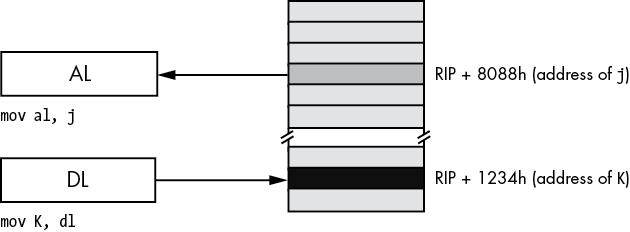
Figure 3-7: PC-relative addressing mode
MASM does not directly encode the address of j or K into the instruction’s operation code (or opcode, the numeric machine encoding of the instruction). Instead, it encodes a signed displacement from the end of the current instruction’s address to the variable’s address in memory. For example, if the next instruction’s opcode is sitting in memory at location 8000h (the end of the current instruction), then MASM will encode the value 88h as a 32-bit signed constant for j in the instruction opcode.
You can also access words and double words on the x86-64 processors by specifying the address of their first byte (see Figure 3-8).
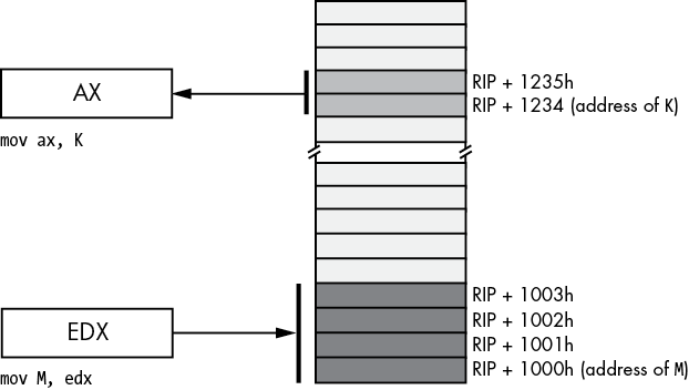
Figure 3-8: Accessing a word or dword by using the PC-relative addressing mode
3.7.2.2 The Register-Indirect Addressing Modes
The x86-64 CPUs let you access memory indirectly through a register by using the register-indirect addressing modes. The term indirect means that the operand is not the actual address, but the operand’s value specifies the memory address to use. In the case of the register-indirect addressing modes, the value held in the register is the address of the memory location to access. For example, the instruction mov [rbx], eax tells the CPU to store EAX’s value at the location whose address is currently in RBX (the square brackets around RBX tell MASM to use the register-indirect addressing mode).
The x86-64 has 16 forms of this addressing mode. The following instructions provide examples of these 16 forms:
mov [reg64], al where reg64 is one of the 64-bit general-purpose registers: RAX, RBX, RCX, RDX, RSI, RDI, RBP, RSP, R8, R9, R10, R11, R12, R13, R14, or R15. This addressing mode references the memory location at the offset found in the register enclosed by brackets.
The register-indirect addressing modes require a 64-bit register. You cannot specify a 32-, 16-, or 8-bit register in the square brackets when using an indirect addressing mode. Technically, you could load a 64-bit register with an arbitrary numeric value and access that location indirectly using the register-indirect addressing mode:
mov rbx, 12345678
mov [rbx], al   ; Attempts to access location 12345678
Unfortunately (or fortunately, depending on how you look at it), this will probably cause the operating system to generate a protection fault because it’s not always legal to access arbitrary memory locations. As it turns out, there are better ways to load the address of an object into a register, and you’ll see those shortly.
You can use the register-indirect addressing modes to access data referenced by a pointer, you can use them to step through array data, and, in general, you can use them whenever you need to modify the address of a variable while your program is running.
The register-indirect addressing mode provides an example of an anonymous variable; when using a register-indirect addressing mode, you refer to the value of a variable by its numeric memory address (the value you load into a register) rather than by the name of the variable.
MASM provides a simple instruction that you can use to take the address of a variable and put it into a 64-bit register, the lea (load effective address) instruction:
lea rbx, jAfter executing this lea instruction, you can use the [rbx] register-indirect addressing mode to indirectly access the value of j.
3.7.2.3 Indirect-Plus-Offset Addressing Mode
The indirect-plus-offset addressing modes compute an effective address by adding a 32-bit signed constant to the value of a 64-bit register.9 The instruction then uses the data at this effective address in memory.
The indirect-plus-offset addressing modes use the following syntax:
mov [reg64 + constant], source
mov [reg64 - constant], source
where reg64 is a 64-bit general-purpose register, constant is a 4-byte constant (±2 billion), and source is a register or constant value.
If constant is 1100h and RBX contains 12345678h, then
mov [rbx + 1100h], alstores AL into the byte at address 12346778h in memory (see Figure 3-9).
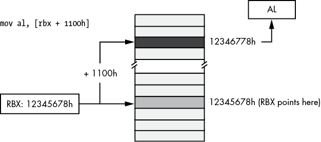
Figure 3-9: Indirect-plus-offset addressing mode
The indirect-plus-offset addressing modes are really handy for accessing fields of classes and records/structures. You will see how to use these addressing modes for that purpose in Chapter 4.
3.7.2.4 Scaled-Indexed Addressing Modes
The scaled-indexed addressing modes are similar to the indexed addressing modes, except the scaled-indexed addressing modes allow you to combine two registers plus a displacement, and multiply the index register by a (scaling) factor of 1, 2, 4, or 8 to compute the effective address by adding in the value of the second register multiplied by the scaling factor. (Figure 3-10 shows an example involving RBX as the base register and RSI as the index register.)
The syntax for the scaled-indexed addressing modes is shown here:
[base_reg64 + index_reg64*scale]
[base_reg64 + index_reg64*scale + displacement]
[base_reg64 + index_reg64*scale - displacement]base_reg64 represents any general-purpose 64-bit register, index_reg64 represents any general-purpose 64-bit register except RSP, and scale must be one of the constants 1, 2, 4, or 8.
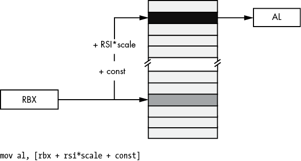
Figure 3-10: Scaled-indexed addressing mode
In Figure 3-10, suppose that RBX contains 1000FF00h, RSI contains 20h, and const is 2000h; then the instruction
mov al, [rbx + rsi*4 + 2000h]will move the byte at address 10011F80h—1000FF00h + (20h × 4) + 2000—into the AL register.
The scaled-indexed addressing modes are useful for accessing array elements that are 2, 4, or 8 bytes each. These addressing modes are also useful for accessing elements of an array when you have a pointer to the beginning of the array.
3.7.3 Large Address Unaware Applications
One advantage of 64-bit addresses is that they can access a frightfully large amount of memory (something like 8TB under Windows). By default, the Microsoft linker (when it links together the C++ and assembly language code) sets a flag named LARGEADDRESSAWARE to true (yes). This makes it possible for your programs to access a huge amount of memory. However, there is a price to be paid for operating in LARGEADDRESSAWARE mode: the const component of the [reg64 + const] addressing mode is limited to 32 bits and cannot span the entire address space.
Because of instruction-encoding limitations, the const value is limited to a signed value in the range ±2GB. This is probably far more than enough when the register contains a 64-bit base address and you want to access a memory location at a fixed offset (less than ±2GB) around that base address. A typical way you would use this addressing mode is as follows:
lea rcx, someStructure
mov al, [rcx+fieldOffset]
Prior to the introduction of 64-bit addresses, the const offset appearing in the (32-bit) indirect-plus-offset addressing mode could span the entire (32-bit) address space. So if you had an array declaration such as
    .data
buf byte   256 dup (?)
you could access elements of this array by using the following addressing mode form:
mov al, buf[ebx] ; EBX was used on 32-bit processorsIf you were to attempt to assemble the instruction mov al, buf[rbx] in a 64-bit program (or any other addressing mode involving buf other than PC-relative), MASM would assemble the code properly, but the linker would report an error:
error LNK2017: 'ADDR32' relocation to 'buf' invalid without /LARGEADDRESSAWARE:NOThe linker is complaining that in an address space exceeding 32 bits, it is impossible to encode the offset to the buf buffer because the machine instruction opcodes provide only a 32-bit offset to hold the address of buf.
However, if we were to artificially limit the amount of memory that our application uses to 2GB, then MASM can encode the 32-bit offset to buf into the machine instruction. As long as we kept our promise and never used any more memory than 2GB, several new variations on the indirect-plus-offset and scaled-indexed addressing modes become possible.
To turn off the large address–aware flag, you need to add an extra command line option to the ml64 command. This is easily done in the build.bat file; let’s create a new build.bat file and call it sbuild.bat. This file will have the following lines:
echo off
ml64 /nologo /c /Zi /Cp %1.asm
cl /nologo /O2 /Zi /utf-8 /EHa /Fe%1.exe c.cpp %1.obj /link /largeaddressaware:no
This set of commands (sbuild.bat for small build) tells MASM to pass a command to the linker that turns off the large address–aware file. MASM, MSVC, and the Microsoft linker will construct an executable file that requires only 32-bit addresses (ignoring the 32 HO bits in the 64-bit registers appearing in addressing modes).
Once you’ve disabled LARGEADDRESSAWARE, several new variants of the indirect-plus-offset and scaled-indexed addressing modes become available to your programs:
variable[reg64]
variable[reg64 + const]
variable[reg64 - const]
variable[reg64 * scale]
variable[reg64 * scale + const]
variable[reg64 * scale - const]
variable[reg64 + reg_not_RSP64 * scale]
variable[reg64 + reg_not_RSP64 * scale + const]
variable[reg64 + reg_not_RSP64 * scale - const]
where variable is the name of an object you’ve declared in your source file by using directives like byte, word, dword, and so on; const is a (maximum 32-bit) constant expression; and scale is 1, 2, 4, or 8. These addressing mode forms use the address of variable as the base address and add in the current value of the 64-bit registers (see Figures 3-11 through 3-16 for examples).
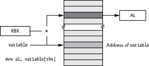
Figure 3-11: Base address form of indirect-plus-offset addressing mode
Although the small address forms (LARGEADDRESSAWARE:NO) are convenient and efficient, they can fail spectacularly if your program ever uses more than 2GB of memory. Should your programs ever grow beyond that point, you will have to completely rewrite every instruction that uses one of these addresses (that uses a global data object as the base address rather than loading the base address into a register). This can be very painful and error prone. Think twice before ever using the LARGEADDRESSAWARE:NO option.
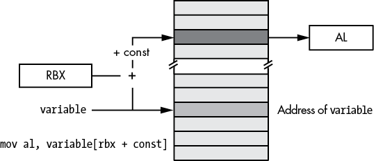
Figure 3-12: Small address plus constant form of indirect-plus-offset addressing mode
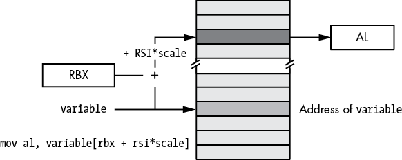
Figure 3-13: Small address form of base-plus-scaled-indexed addressing mode
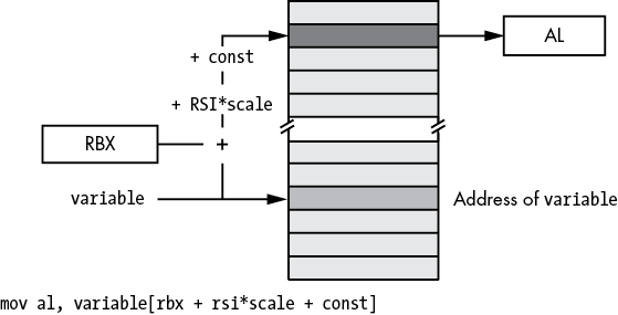
Figure 3-14: Small address form of base-plus-scaled-indexed-plus-constant addressing mode
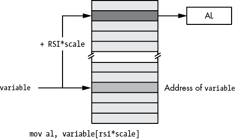
Figure 3-15: Small address form of scaled-indexed addressing mode
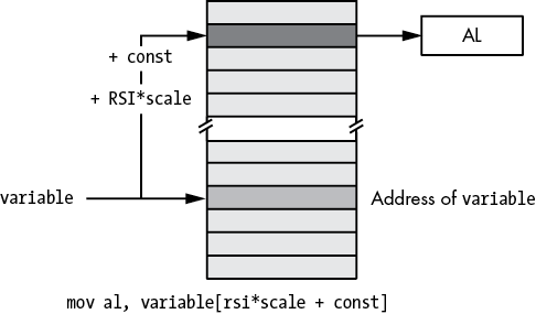
Figure 3-16: Small address form of scaled-indexed-plus-constant addressing mode
3.8 Address Expressions
Often, when accessing variables and other objects in memory, we need to access memory locations immediately before or after a variable rather than the memory at the address specified by the variable. For example, when accessing an element of an array or a field of a structure/record, the exact element or field is probably not at the address of the variable itself. Address expressions provide a mechanism to attach an arithmetic expression to an address to access memory around a variable’s address.
This book considers an address expression to be any legal x86-64 addressing mode that includes a displacement (that is, variable name) or an offset. For example, the following are legal address expressions:
[reg64 + offset]
[reg64 + reg_not_RSP64 * scale + offset]
Consider the following legal MASM syntax for a memory address, which isn’t actually a new addressing mode but simply an extension of the PC-relative addressing mode:
variable_name[offset]This extended form computes its effective address by adding the constant offset within the brackets to the variable’s address. For example, the instruction mov al, Address[3] loads the AL register with the byte in memory that is 3 bytes beyond the Address object (see Figure 3-17).
The offset value in these examples must be a constant. If index is an int32 variable, then variable[index] is not a legal address expression. If you wish to specify an index that varies at runtime, you must use one of the indirect or scaled-indexed addressing modes.
Another important thing to remember is that the offset in Address[offset] is a byte address. Although this syntax is reminiscent of array indexing in a high-level language like C/C++ or Java, this does not properly index into an array of objects unless Address is an array of bytes.
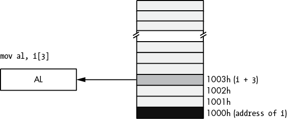
Figure 3-17: Using an address expression to access data beyond a variable
Until this point, the offset in all the addressing mode examples has always been a single numeric constant. However, MASM also allows a constant expression anywhere an offset is legal. A constant expression consists of one or more constant terms manipulated by operators such as addition, subtraction, multiplication, division, modulo, and a wide variety of others. Most address expressions, however, will involve only addition, subtraction, multiplication, and sometimes division. Consider the following example:
mov al, X[2*4 + 1]This instruction will move the byte at address X + 9 into the AL register.
The value of an address expression is always computed at compile time, never while the program is running. When MASM encounters the preceding instruction, it calculates 2 × 4 + 1 on the spot and adds this result to the base address of X in memory. MASM encodes this single sum (base address of X plus 9) as part of the instruction; MASM does not emit extra instructions to compute this sum for you at runtime (which is good, because doing so would be less efficient). Because MASM computes the value of address expressions at compile time, all components of the expression must be constants because MASM cannot know the runtime value of a variable while it is compiling the program.
Address expressions are useful for accessing the data in memory beyond a variable, particularly when you’ve used the byte, word, dword, and so on, statements in a .data or .const section to tack on additional bytes after a data declaration. For example, consider the program in Listing 3-1 that uses address expressions to access the four consecutive bytes associated with variable i.
; Listing 3-1

; Demonstrate address expressions.

        option  casemap:none

nl      =       10  ; ASCII code for newline

                .const
ttlStr          byte    'Listing 3-1', 0
fmtStr1         byte    'i[0]=%d ', 0
fmtStr2         byte    'i[1]=%d ', 0
fmtStr3         byte    'i[2]=%d ', 0
fmtStr4         byte    'i[3]=%d',nl, 0

        .data
i       byte    0, 1, 2, 3

        .code
        externdef printf:proc

; Return program title to C++ program:

         public getTitle
getTitle proc
         lea rax, ttlStr
         ret
getTitle endp

; Here is the "asmMain" function.

        public  asmMain
asmMain proc
        push    rbx

; "Magic" instruction offered without
; explanation at this point:

        sub     rsp, 48

        lea     rcx, fmtStr1
        movzx   rdx, i[0]
        call    printf

        lea     rcx, fmtStr2
        movzx   rdx, i[1]
        call    printf

        lea     rcx, fmtStr3
        movzx   rdx, i[2]
        call    printf

        lea     rcx, fmtStr4
        movzx   rdx, i[3]
        call    printf

        add     rsp, 48
        pop     rbx
        ret     ; Returns to caller
asmMain endp
        end
Listing 3-1: Demonstration of address expressions
Here’s the output from the program:
C:\>build listing3-1

C:\>echo off
 Assembling: listing3-1.asm
c.cpp

C:\>listing3-1
Calling Listing 3-1:
i[0]=0 i[1]=1 i[2]=2 i[3]=3
Listing 3-1 terminated
The program in Listing 3-1 displays the four values 0, 1, 2, and 3 as though they were array elements. This is because the value at the address of i is 0. The address expression i[1] tells MASM to fetch the byte appearing at i’s address plus 1. This is the value 1, because the byte statement in this program emits the value 1 to the .data segment immediately after the value 0. Likewise for i[2] and i[3], this program displays the values 2 and 3.
Note that MASM also provides a special operator, this, that returns the current location counter (current position) within a section. You can use the this operator to represent the address of the current instruction in an address expression. See “Constant Expressions” in Chapter 4 for more details.
3.9 The Stack Segment and the push and pop Instructions
The x86-64 maintains the stack in the stack segment of memory. The stack is a dynamic data structure that grows and shrinks according to certain needs of the program. The stack also stores important information about the program, including local variables, subroutine information, and temporary data.
The x86-64 controls its stack via the RSP (stack pointer) register. When your program begins execution, the operating system initializes RSP with the address of the last memory location in the stack memory segment. Data is written to the stack segment by “pushing” data onto the stack and “popping” data off the stack.
3.9.1 The Basic push Instruction
Here’s the syntax for the x86-64 push instruction:
push  reg16
push  reg64
push  memory16
push  memory64
pushw constant16
push  constant32  ; Sign extends constant32 to 64 bits
These six forms allow you to push 16-bit or 64-bit registers, 16-bit or 64-bit memory locations, and 16-bit or 64-bit constants, but not 32-bit registers, memory locations, or constants.
The push instruction does the following:
RSP   := RSP - size_of_register_or_memory_operand (2 or 8)
[RSP] := operand's_value
For example, assuming that RSP contains 00FF_FFFCh, the instruction push rax will set RSP to 00FF_FFE4h and store the current value of RAX into memory location 00FF_FFE04, as Figures 3-18 and 3-19 show.
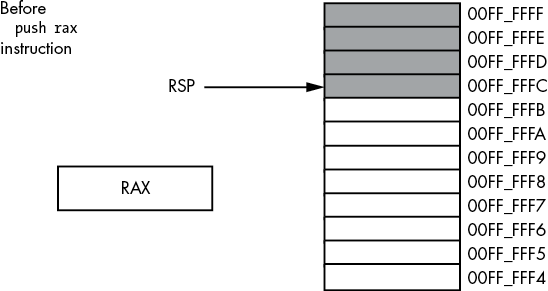
Figure 3-18: Stack segment before the push rax operation
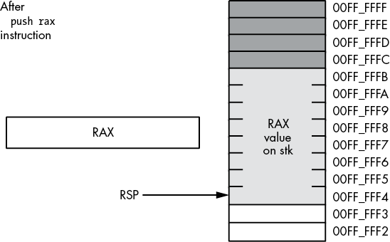
Figure 3-19: Stack segment after the push rax operation
Although the x86-64 supports 16-bit push operations, their primary use is in 16-bit environments such as Microsoft Disk Operating System (MS-DOS). For maximum performance, the stack pointer’s value should always be a multiple of eight; indeed, your program may malfunction under a 64-bit OS if RSP contains a value that is not a multiple of eight. The only practical reason for pushing fewer than 8 bytes at a time on the stack is to build up a quad word via four successive word pushes.
3.9.2 The Basic pop Instruction
To retrieve data you’ve pushed onto the stack, you use the pop instruction. The basic pop instruction allows the following forms:
pop reg16
pop reg64
pop memory16
pop memory64
Like the push instruction, the pop instruction supports only 16-bit and 64-bit operands; you cannot pop an 8-bit or 32-bit value from the stack. As with the push instruction, you should avoid popping 16-bit values (unless you do four 16-bit pops in a row) because 16-bit pops may leave the RSP register containing a value that is not a multiple of eight. One major difference between push and pop is that you cannot pop a constant value (which makes sense, because the operand for push is a source operand, while the operand for pop is a destination operand).
Formally, here’s what the pop instruction does:
operand := [RSP]
RSP     := RSP + size_of_operand (2 or 8)
As you can see, the pop operation is the converse of the push operation. Note that the pop instruction copies the data from memory location [RSP] before adjusting the value in RSP. See Figures 3-20 and 3-21 for details on this operation.
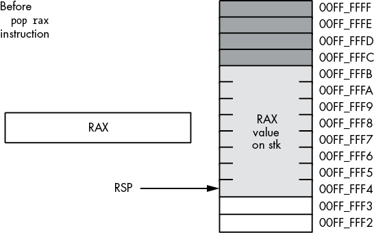
Figure 3-20: Memory before a pop rax operation
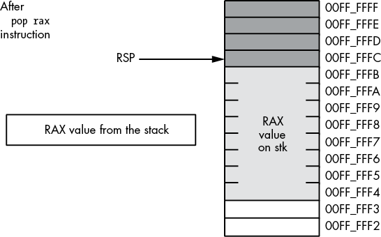
Figure 3-21: Memory after the pop rax operation
The value popped from the stack is still present in memory. Popping a value does not erase the value in memory; it just adjusts the stack pointer so that it points at the next value above the popped value. However, you should never attempt to access a value you’ve popped off the stack. The next time something is pushed onto the stack, the popped value will be obliterated. Because your code isn’t the only thing that uses the stack (for example, the operating system uses the stack, as do subroutines), you cannot rely on data remaining in stack memory once you’ve popped it off the stack.
3.9.3 Preserving Registers with the push and pop Instructions
Perhaps the most common use of the push and pop instructions is to save register values during intermediate calculations. Because registers are the best place to hold temporary values, and registers are also needed for the various addressing modes, it is easy to run out of registers when writing code that performs complex calculations. The push and pop instructions can come to your rescue when this happens.
Consider the following program outline:
  Some instructions that use the RAX register

  Some instructions that need to use RAX, for a
  different purpose than the above instructions

  Some instructions that need the original value in RAX
The push and pop instructions are perfect for this situation. By inserting a push instruction before the middle sequence and a pop instruction after the middle sequence, you can preserve the value in RAX across those calculations:
  Some instructions that use the RAX register

     push rax

  Some instructions that need to use RAX, for a
  different purpose than the above instructions

     pop rax

  Some instructions that need the original value in RAX
This push instruction copies the data computed in the first sequence of instructions onto the stack. Now the middle sequence of instructions can use RAX for any purpose it chooses. After the middle sequence of instructions finishes, the pop instruction restores the value in RAX so the last sequence of instructions can use the original value in RAX.
3.10 The Stack Is a LIFO Data Structure
You can push more than one value onto the stack without first popping previous values off the stack. However, the stack is a last-in, first-out (LIFO) data structure, so you must be careful how you push and pop multiple values. For example, suppose you want to preserve RAX and RBX across a block of instructions; the following code demonstrates the obvious way to handle this:
push rax
push rbx
  Code that uses RAX and RBX goes here
pop rax
pop rbx
Unfortunately, this code will not work properly! Figures 3-22 through 3-25 show the problem. Because this code pushes RAX first and RBX second, the stack pointer is left pointing at RBX’s value on the stack. When the pop rax instruction comes along, it removes the value that was originally in RBX from the stack and places it in RAX! Likewise, the pop rbx instruction pops the value that was originally in RAX into the RBX register. The result is that this code manages to swap the values in the registers by popping them in the same order that it pushes them.
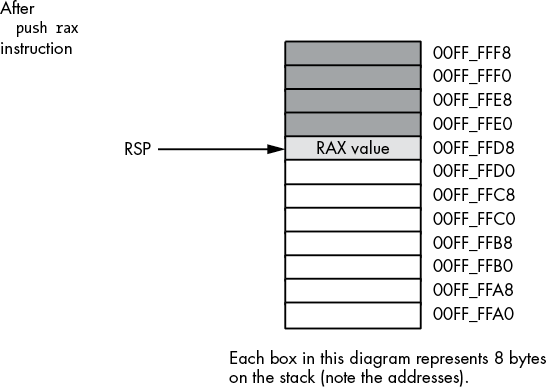
Figure 3-22: Stack after pushing RAX
To rectify this problem, you must note that the stack is a LIFO data structure, so the first thing you must pop is the last thing you push onto the stack. Therefore, you must always observe the following maxim: always pop values in the reverse order that you push them.
The correction to the previous code is shown here:
push rax
push rbx
  Code that uses RAX and RBX goes here
pop rbx
pop rax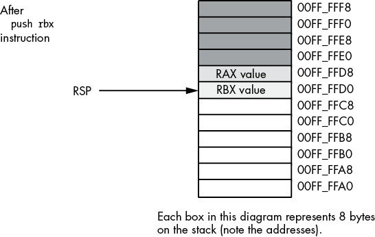
Figure 3-23: Stack after pushing RBX
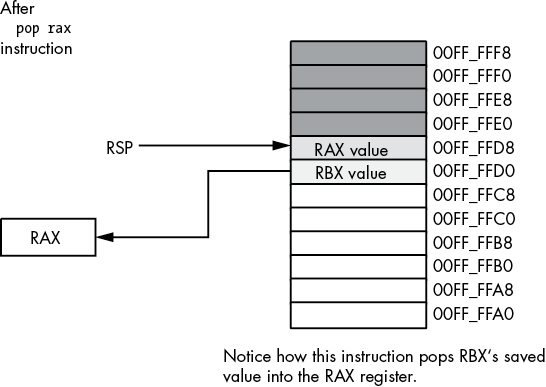
Figure 3-24: Stack after popping RAX
Another important maxim to remember is this: always pop exactly the same number of bytes that you push. This generally means that the number of pushes and pops must exactly agree. If you have too few pops, you will leave data on the stack, which may confuse the running program. If you have too many pops, you will accidentally remove previously pushed data, often with disastrous results.
A corollary to the preceding maxim is be careful when pushing and popping data within a loop. Often it is quite easy to put the pushes in a loop and leave the pops outside the loop (or vice versa), creating an inconsistent stack. Remember, it is the execution of the push and pop instructions that matters, not the number of push and pop instructions that appear in your program. At runtime, the number (and order) of the push instructions the program executes must match the number (and reverse order) of the pop instructions.
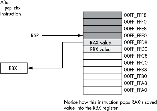
Figure 3-25: Stack after popping RBX
One final thing to note: the Microsoft ABI requires the stack to be aligned on a 16-byte boundary. If you push and pop items on the stack, make sure that the stack is aligned on a 16-byte boundary before calling any functions or procedures that adhere to the Microsoft ABI (and require the stack to be aligned on a 16-byte boundary).
3.11 Other push and pop Instructions
The x86-64 provides four additional push and pop instructions in addition to the basic ones:
pushfpopfpushfqpopfq
The pushf, pushfq, popf, and popfq instructions push and pop the RFLAGS register. These instructions allow you to preserve condition code and other flag settings across the execution of a sequence of instructions. Unfortunately, unless you go to a lot of trouble, it is difficult to preserve individual flags. When using the pushf(q) and popf(q) instructions, it’s an all-or-nothing proposition: you preserve all the flags when you push them; you restore all the flags when you pop them.
You should really use the pushfq and popfq instructions to push the full 64-bit version of the RFLAGS register (rather than pushing only the 16-bit FLAGs portion). Although the extra 48 bits you push and pop are essentially ignored when writing applications, you still want to keep the stack aligned by pushing and popping only quad words.
3.12 Removing Data from the Stack Without Popping It
Quite often you may discover that you’ve pushed data onto the stack that you no longer need. Although you could pop the data into an unused register or memory location, there is an easier way to remove unwanted data from the stack—simply adjust the value in the RSP register to skip over the unwanted data on the stack.
Consider the following dilemma (in pseudocode, not actual assembly language):
push rax
push rbx

  Some code that winds up computing some values we want to keep
  in RAX and RBX

if(Calculation_was_performed) then

    ; Whoops, we don't want to pop RAX and RBX!
    ; What to do here?

else

    ; No calculation, so restore RAX, RBX.

    pop rbx
    pop rax

endif;
Within the then section of the if statement, this code wants to remove the old values of RAX and RBX without otherwise affecting any registers or memory locations. How can we do this?
Because the RSP register contains the memory address of the item on the top of the stack, we can remove the item from the top of the stack by adding the size of that item to the RSP register. In the preceding example, we wanted to remove two quad-word items from the top of the stack. We can easily accomplish this by adding 16 to the stack pointer (see Figures 3-26 and 3-27 for the details):
push rax
push rbx

  Some code that winds up computing some values we want to keep
  in RAX and RBX

if(Calculation_was_performed) then

    ; Remove unneeded RAX/RBX values
    ; from the stack.

    add rsp, 16

else

    ; No calculation, so restore RAX, RBX.

    pop rbx
    pop rax

endif;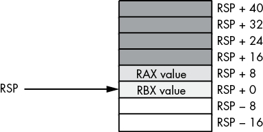
Figure 3-26: Removing data from the stack, before add rsp, 16
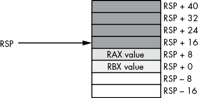
Figure 3-27: Removing data from the stack, after add rsp, 16
Effectively, this code pops the data off the stack without moving it anywhere. Also note that this code is faster than two dummy pop instructions because it can remove any number of bytes from the stack with a single add instruction.
3.13 Accessing Data You’ve Pushed onto the Stack Without Popping It
Once in a while, you will push data onto the stack and will want to get a copy of that data’s value, or perhaps you will want to change that data’s value without actually popping the data off the stack (that is, you wish to pop the data off the stack at a later time). The x86-64 [reg64 ± offset] addressing mode provides the mechanism for this.
Consider the stack after the execution of the following two instructions (see Figure 3-28):
push rax
push rbx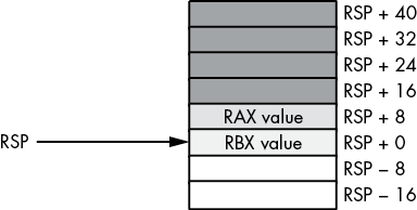
Figure 3-28: Stack after pushing RAX and RBX
If you wanted to access the original RBX value without removing it from the stack, you could cheat and pop the value and then immediately push it again. Suppose, however, that you wish to access RAX’s old value or another value even further up the stack. Popping all the intermediate values and then pushing them back onto the stack is problematic at best, impossible at worst. However, as you will notice from Figure 3-28, each value pushed on the stack is at a certain offset from the RSP register in memory. Therefore, we can use the [rsp ± offset] addressing mode to gain direct access to the value we are interested in. In the preceding example, you can reload RAX with its original value by using this single instruction:
mov rax, [rsp + 8]This code copies the 8 bytes starting at memory address rsp + 8 into the RAX register. This value just happens to be the previous value of RAX that was pushed onto the stack. You can use this same technique to access other data values you’ve pushed onto the stack.
The previous section pointed out how to remove data from the stack by adding a constant to the RSP register. That pseudocode example could probably be written more safely as this:
push rax
push rbx

  Some code that winds up computing some values we want to keep
  in RAX and RBX

if(Calculation_was_performed) then

  Overwrite saved values on stack with
  new RAX/RBX values (so the pops that
  follow won't change the values in RAX/RBX)

     mov [rsp + 8], rax
     mov [rsp], rbx

endif
pop rbx
pop rax
In this code sequence, the calculated result was stored over the top of the values saved on the stack. Later, when the program pops the values, it loads these calculated values into RAX and RBX.
3.14 Microsoft ABI Notes
About the only feature this chapter introduces that affects the Microsoft ABI is data alignment. As a general rule, the Microsoft ABI requires all data to be aligned on a natural boundary for that data object. A natural boundary is an address that is a multiple of the object’s size (up to 16 bytes). Therefore, if you intend to pass a word/sword, dword/sdword, or qword/sqword value to a C++ procedure, you should attempt to align that object on a 2-, 4-, or 8-byte boundary, respectively.
When calling code written in a Microsoft ABI–aware language, you must ensure that the stack is aligned on a 16-byte boundary before issuing a call instruction. This can severely limit the usefulness of the push and pop instructions. If you use the push instructions to save a register’s value prior to a call, you must make sure you push two (64-bit) values, or otherwise make sure the RSP address is a multiple of 16 bytes, prior to making the call. Chapter 5 explores this issue in greater detail.
3.15 For More Information
An older, 16-bit version of my book The Art of Assembly Language Programming can be found at https://artofasm.randallhyde.com/. In that text, you will find information about the 8086 16-bit addressing modes and segmentation. The published edition of that book (No Starch Press, 2010) covers the 32-bit addressing modes. Of course, the Intel x86 documentation (found at http://www.intel.com/) provides complete information on x86-64 address modes and machine instruction encoding.
3.16 Test Yourself
- The PC-relative addressing mode indexes off which 64-bit register?
- What does opcode stand for?
- What type of data is the PC-relative addressing mode typically used for?
- What is the address range of the PC-relative addressing mode?
- In a register-indirect addressing mode, what does the register contain?
- Which of the following registers is valid for use with the register-indirect addressing mode?
- AL
- AX
- EAX
- RAX
- What instruction would you normally use to load the address of a memory object into a register?
- What is an effective address?
- What scaling values are legal with the scaled-indexed addressing mode?
- What is the memory limitation on a
LARGEADDRESSAWARE:NOapplication? - What is the advantage of using the
LARGEADDRESSAWARE:NOoption when compiling a program? - What is the difference between the
.datasection and the.data?section? - Which (standard MASM) memory sections are read-only?
- Which (standard MASM) memory sections are readable and writable?
- What is the location counter?
- Explain how to use the
labeldirective to coerce data to a different type. - Explain what happens if two (or more)
.datasections appear in a MASM source file. - How would you align a variable in the
.datasection to an 8-byte boundary? - What does MMU stand for?
- If
bis a byte variable in read/write memory, explain how amov ax, binstruction could cause a general protection fault. - What is an address expression?
- What is the purpose of the MASM PTR operator?
- What is the difference between a big-endian value and a little-endian value?
- If AX contains a big-endian value, what instruction could you use to convert it to a little-endian value?
- If EAX contains a little-endian value, what instruction could you use to convert it to a big-endian value?
- If RAX contains a big-endian value, what instruction could you use to convert it to a little-endian value?
- Explain, step by step, what the
push raxinstruction does. - Explain, step by step, what the
pop raxinstruction does. - When using the
pushandpopinstructions to preserve registers, you must always pop the registers in the order that you pushed them. - What does LIFO stand for?
- How do you access data on the stack without using the
pushandpopinstructions? - How can pushing RAX onto the stack before calling a Windows ABI–compatible function create problems?