11
SIMD Instructions

This chapter discusses the vector instructions on the x86-64. This special class of instructions provides parallel processing, traditionally known as single-instruction, multiple-data (SIMD) instructions because, quite literally, a single instruction operates on several pieces of data concurrently. As a result of this concurrency, SIMD instructions can often execute several times faster (in theory, as much as 32 to 64 times faster) than the comparable single-instruction, single-data (SISD), or scalar, instructions that compose the standard x86-64 instruction set.
The x86-64 actually provides three sets of vector instructions: the Multimedia Extensions (MMX) instruction set, the Streaming SIMD Extensions (SSE) instruction set, and the Advanced Vector Extensions (AVX) instruction set. This book does not consider the MMX instructions as they are obsolete (SSE equivalents exist for the MMX instructions).
The x86-64 vector instruction set (SSE/AVX) is almost as large as the scalar instruction set. A whole book could be written about SSE/AVX programming and algorithms. However, this is not that book; SIMD and parallel algorithms are an advanced subject beyond the scope of this book, so this chapter settles for introducing a fair number of SSE/AVX instructions and leaves it at that.
This chapter begins with some prerequisite information. First, it begins with a discussion of the x86-64 vector architecture and streaming data types. Then, it discusses how to detect the presence of various vector instructions (which are not present on all x86-64 CPUs) by using the cpuid instruction. Because most vector instructions require special memory alignment for data operands, this chapter also discusses MASM segments.
11.1 The SSE/AVX Architectures
Let’s begin by taking a quick look at the SSE and AVX features in the x64-86 CPUs. The SSE and AVX instructions have several variants: the original SSE, plus SSE2, SSE3, SSE3, SSE4 (SSE4.1 and SSE4.2), AVX, AVX2 (AVX and AVX2 are sometimes called AVX-256), and AVX-512. SSE3 was introduced along with the Pentium 4F (Prescott) CPU, Intel’s first 64-bit CPU. Therefore, you can assume that all Intel 64-bit CPUs support the SSE3 and earlier SIMD instructions.
The SSE/AVX architectures have three main generations:
- The SSE architecture, which (on 64-bit CPUs) provided sixteen 128-bit XMM registers supporting integer and floating-point data types
- The AVX/AVX2 architecture, which supported sixteen 256-bit YMM registers (also supporting integer and floating-point data types)
- The AVX-512 architecture, which supported up to thirty-two 512-bit ZMM registers
As a general rule, this chapter sticks to AVX2 and earlier instructions in its examples. Please see the Intel and AMD CPU manuals for a discussion of the additional instruction set extensions such as AVX-512. This chapter does not attempt to describe every SSE or AVX instruction. Most streaming instructions have very specialized purposes and aren’t particularly useful in generic applications.
11.2 Streaming Data Types
The SSE and AVX programming models support two basic data types: scalars and vectors. Scalars hold one single- or double-precision floating-point value. Vectors hold multiple floating-point or integer values (between 2 and 32 values, depending on the scalar data type of byte, word, dword, qword, single precision, or double precision, and the register and memory size of 128 or 256 bits).
The XMM registers (XMM0 to XMM15) can hold a single 32-bit floating-point value (a scalar) or four single-precision floating-point values (a vector). The YMM registers (YMM0 to YMM15) can hold eight single-precision (32-bit) floating-point values (a vector); see Figure 11-1.

Figure 11-1: Packed and scalar single-precision floating-point data type
The XMM registers can hold a single double-precision scalar value or a vector containing a pair of double-precision values. The YMM registers can hold a vector containing four double-precision floating-point values, as shown in Figure 11-2.

Figure 11-2: Packed and scalar double-precision floating-point type
The XMM registers can hold 16 byte values (YMM registers can hold 32 byte values), allowing the CPU to perform 16 (32) byte-sized computations with one instruction (Figure 11-3).

Figure 11-3: Packed byte data type
The XMM registers can hold eight word values (YMM registers can hold sixteen word values), allowing the CPU to perform eight (sixteen) 16-bit word-sized integer computations with one instruction (Figure 11-4).

Figure 11-4: Packed word data type
The XMM registers can hold four dword values (YMM registers can hold eight dword values), allowing the CPU to perform four (eight) 32-bit dword-sized integer computations with one instruction (Figure 11-5).

Figure 11-5: Packed double-word data type
The XMM registers can hold two qword values (YMM registers can hold four qword values), allowing the CPU to perform two (four) 64-bit qword computations with one instruction (Figure 11-6).

Figure 11-6: Packed quad-word data type
Intel’s documentation calls the vector elements in an XMM and a YMM register lanes. For example, a 128-bit XMM register has 16 bytes. Bits 0 to 7 are lane 0, bits 8 to 15 are lane 1, bits 16 to 23 are lane 2, . . . , and bits 120 to 127 are lane 15. A 256-bit YMM register has 32 byte-sized lanes, and a 512-bit ZMM register has 64 byte-sized lanes.
Similarly, a 128-bit XMM register has eight word-sized lanes (lanes 0 to 7). A 256-bit YMM register has sixteen word-sized lanes (lanes 0 to 15). On AVX-512-capable CPUs, a ZMM register (512 bits) has thirty-two word-sized lanes, numbered 0 to 31.
An XMM register has four dword-sized lanes (lanes 0 to 3); it also has four single-precision (32-bit) floating-point lanes (also numbered 0 to 3). A YMM register has eight dword or single-precision lanes (lanes 0 to 7). An AVX2 ZMM register has sixteen dword or single-precision-sized lanes (numbers 0 to 15).
XMM registers support two qword-sized lanes (or two double-precision lanes), numbered 0 to 1. As expected, a YMM register has twice as many (four lanes, numbered 0 to 3), and an AVX2 ZMM register has four times as many lanes (0 to 7).
Several SSE/AVX instructions refer to various lanes within these registers. In particular, the shuffle and unpack instructions allow you to move data between lanes in SSE and AVX operands. See “The Shuffle and Unpack Instructions” on page 625 for examples of lane usage.
11.3 Using cpuid to Differentiate Instruction Sets
Intel introduced the 8086 (and shortly thereafter, the 8088) microprocessor in 1978. With almost every succeeding CPU generation, Intel added new instructions to the instruction set. Until this chapter, this book has used instructions that are generally available on all x86-64 CPUs (Intel and AMD). This chapter presents instructions that are available only on later-model x86-64 CPUs. To allow programmers to determine which CPU their applications were using so they could dynamically avoid using newer instructions on older processors, Intel introduced the cpuid instruction.
The cpuid instruction expects a single parameter (called a leaf function) passed in the EAX register. It returns various pieces of information about the CPU in different 32-bit registers based on the value passed in EAX. An application can test the return information to see if certain CPU features are available.
As Intel introduced new instructions, it changed the behavior of cpuid to reflect those changes. Specifically, Intel changed the range of values a program could legally pass in EAX to cpuid; this is known as the highest function supported. As a result, some 64-bit CPUs accept only values in the range 0h to 05h. The instructions this chapter discusses may require passing values in the range 0h to 07h. Therefore, the first thing you have to do when using cpuid is to verify that it accepts EAX = 07h as a valid parameter.
To determine the highest function supported, you load EAX with 0 or 8000_0000h and execute the cpuid instruction (all 64-bit CPUs support these two function values). The return value is the maximum you can pass to cpuid in EAX. The Intel and AMD documentation (also see https://en.wikipedia.org/wiki/CPUID) will list the values cpuid returns for various CPUs; for the purposes of this chapter, we need only verify that the highest function supported is 01h (which is true for all 64-bit CPUs) or 07h for certain instructions.
In addition to providing the highest function supported, the cpuid instruction with EAX = 0h (or 8000_0002h) also returns a 12-character vendor ID in the EBX, ECX, and EDX registers. For x86-64 chips, this will be either of the following:
- GenuineIntel (EBX is 756e_6547h, EDX is 4965_6e69h, and ECX is 6c65_746eh)
- AuthenticAMD (EBX is 6874_7541h, EDX is 6974_6E65h, and ECX is 444D_4163h)
To determine if the CPU can execute most SSE and AVX instructions, you must execute cpuid with EAX = 01h and test various bits placed in the ECX register. For a few of the more advanced features (advanced bit-manipulation functions and AVX2 instructions), you’ll need to execute cpuid with EAX = 07h and check the results in the EBX register. The cpuid instruction (with EAX = 1) returns an interesting SSE/AVX feature flag in the following bits in ECX, as shown in Table 11-1; with EAX = 07h, it returns the bit manipulation or AVX2 flag in EBX, as shown in Table 11-2. If the bit is set, the CPU supports the specific instruction(s).
Table 11-1: Intel cpuid Feature Flags (EAX = 1)
| Bit | ECX |
| 0 | SSE3 support |
| 1 | PCLMULQDQ support |
| 9 | SSSE3 support |
| 19 | CPU supports SSE4.1 instructions |
| 20 | CPU supports SSE4.2 instructions |
| 28 | Advanced Vector Extensions |
Table 11-2: Intel cpuid Extended Feature Flags (EAX = 7, ECX = 0)
| Bit | EBX |
| 3 | Bit Manipulation Instruction Set 1 |
| 5 | Advanced Vector Extensions 2 (AVX2) |
| 8 | Bit Manipulation Instruction Set 2 |
Listing 11-1 queries the vendor ID and basic feature flags on a CPU.
; Listing 11-1

; CPUID Demonstration.

        option  casemap:none

nl          =       10

            .const
ttlStr      byte    "Listing 11-1", 0

            .data
maxFeature  dword   ?
VendorID    byte    14 dup (0)

            .code
            externdef printf:proc

; Return program title to C++ program:

            public  getTitle
getTitle    proc
            lea     rax, ttlStr
            ret
getTitle    endp

; Used for debugging:

print       proc
            push    rax
            push    rbx
            push    rcx
            push    rdx
            push    r8
            push    r9
            push    r10
            push    r11

            push    rbp
            mov     rbp, rsp
            sub     rsp, 40
            and     rsp, -16

            mov     rcx, [rbp + 72]   ; Return address
            call    printf

            mov     rcx, [rbp + 72]
            dec     rcx
skipTo0:    inc     rcx
            cmp     byte ptr [rcx], 0
            jne     skipTo0
            inc     rcx
            mov     [rbp + 72], rcx

            leave
            pop     r11
            pop     r10
            pop     r9
            pop     r8
            pop     rdx
            pop     rcx
            pop     rbx
            pop     rax
            ret
print       endp

; Here is the "asmMain" function.

            public  asmMain
asmMain     proc
            push    rbx
            push    rbp
            mov     rbp, rsp
            sub     rsp, 56         ; Shadow storage

            xor     eax, eax
            cpuid
            mov     maxFeature, eax
            mov     dword ptr VendorID, ebx
            mov     dword ptr VendorID[4], edx
            mov     dword ptr VendorID[8], ecx

            lea     rdx, VendorID
            mov     r8d, eax
            call    print
            byte    "CPUID(0): Vendor ID='%s',  "
            byte    "max feature=0%xh", nl, 0

; Leaf function 1 is available on all CPUs that support
; CPUID, no need to test for it.

            mov     eax, 1
            cpuid
            mov     r8d, edx
            mov     edx, ecx
            call    print
            byte    "cpuid(1), ECX=%08x, EDX=%08x", nl, 0

; Most likely, leaf function 7 is supported on all modern CPUs
; (for example, x86-64), but we'll test its availability nonetheless.

            cmp     maxFeature, 7
            jb      allDone

            mov     eax, 7
            xor     ecx, ecx
            cpuid
            mov     edx, ebx
            mov     r8d, ecx
            call    print
            byte    "cpuid(7), EBX=%08x, ECX=%08x", nl, 0

allDone:    leave
            pop     rbx
            ret     ; Returns to caller
asmMain     endp
            end
Listing 11-1: cpuid demonstration program
On an old MacBook Pro Retina with an Intel i7-3720QM CPU, running under Parallels, you get the following output:
C:\>build listing11-1

C:\>echo off
 Assembling: listing11-1.asm
c.cpp

C:\>listing11-1
Calling Listing 11-1:
CPUID(0): Vendor ID='GenuineIntel', max feature=0dh
cpuid(1), ECX=ffba2203, EDX=1f8bfbff
cpuid(7), EBX=00000281, ECX=00000000
Listing 11-1 terminated
This CPU supports SSE3 instructions (bit 0 of ECX is 1), SSE4.1 and SSE4.2 instructions (bits 19 and 20 of ECX are 1), and the AVX instructions (bit 28 is 1). Those, largely, are the instructions this chapter describes. Most modern CPUs will support these instructions (the i7-3720QM was released by Intel in 2012). The processor doesn’t support some of the more interesting extended features on the Intel instruction set (the extended bit-manipulation instructions and the AVX2 instruction set). Programs using those instructions will not execute on this (ancient) MacBook Pro.
Running this on a more recent CPU (an iMac Pro 10-core Intel Xeon W-2150B) produces the following output:
C:\>listing11-1
Calling Listing 11-1:
CPUID(0): Vendor ID='GenuineIntel', max feature=016h
cpuid(1), ECX=fffa3203, EDX=1f8bfbff
cpuid(7), EBX=d09f47bb, ECX=00000000
Listing 11-1 terminated
As you can see, looking at the extended feature bits, the newer Xeon CPU does support these additional instructions. The code fragment in Listing 11-2 provides a quick modification to Listing 11-1 that tests for the availability of the BMI1 and BMI2 bit-manipulation instruction sets (insert the following code right before the allDone label in Listing 11-1).
; Test for extended bit manipulation instructions
; (BMI1 and BMI2):

            and     ebx, 108h       ; Test bits 3 and 8
            cmp     ebx, 108h       ; Both must be set
            jne     Unsupported
            call    print
            byte    "CPU supports BMI1 & BMI2", nl, 0
            jmp     allDone

Unsupported:
            call    print
            byte    "CPU does not support BMI1 & BMI2 "
            byte    "instructions", nl, 0

allDone:    leave
            pop     rbx
            ret     ; Returns to caller
asmMain     endp
Listing 11-2: Test for BMI1 and BMI2 instruction sets
Here’s the build command and program output on the Intel i7-3720QM CPU:
C:\>build listing11-2

C:\>echo off
 Assembling: listing11-2.asm
c.cpp

C:\>listing11-2
Calling Listing 11-2:
CPUID(0): Vendor ID='GenuineIntel', max feature=0dh
cpuid(1), ECX=ffba2203, EDX=1f8bfbff
cpuid(7), EBX=00000281, ECX=00000000
CPU does not support BMI1 & BMI2 instructions
Listing 11-2 terminated
Here’s the same program running on the iMac Pro (Intel Xeon W-2150B):
C:\>listing11-2
Calling Listing 11-2:
CPUID(0): Vendor ID='GenuineIntel', max feature=016h
cpuid(1), ECX=fffa3203, EDX=1f8bfbff
cpuid(7), EBX=d09f47bb, ECX=00000000
CPU supports BMI1 & BMI2
Listing 11-2 terminated
11.4 Full-Segment Syntax and Segment Alignment
As you will soon see, SSE and AVX memory data require alignment on 16-, 32-, and even 64-byte boundaries. Although you can use the align directive to align data (see “MASM Support for Data Alignment” in Chapter 3), it doesn’t work beyond 16-byte alignment when using the simplified segment directives presented thus far in this book. If you need alignment beyond 16 bytes, you have to use MASM full-segment declarations.
If you want to create a segment with complete control over segment attributes, you need to use the segment and ends directives.1 The generic syntax for a segment declaration is as follows:
segname  segment readonly alignment 'class'
         statements
segname  ends
segname is an identifier. This is the name of the segment (which must also appear before the closing ends directive). It need not be unique; you can have several segment declarations that share the same name. MASM will combine segments with the same name when emitting code to the object file. Avoid the segment names _TEXT, _DATA, _BSS, and _CONST, as MASM uses these names for the .code, .data, .data?, and .const directives, respectively.
The readonly option is either blank or the MASM-reserved word readonly. This is a hint to MASM that the segment will contain read-only (constant) data. If you attempt to (directly) store a value into a variable that you declare in a read-only segment, MASM will complain that you cannot modify a read-only segment.
The alignment option is also optional and allows you to specify one of the following options:
byteworddwordparapagealign(n)(n is a constant that must be a power of 2)
The alignment options tell MASM that the first byte emitted for this particular segment must appear at an address that is a multiple of the alignment option. The byte, word, and dword reserved words specify 1-, 2-, or 4-byte alignments. The para alignment option specifies paragraph alignment (16 bytes). The page alignment option specifies an address alignment of 256 bytes. Finally, the align(n) alignment option lets you specify any address alignment that is a power of 2 (1, 2, 4, 8, 16, 32, and so on).
The default segment alignment, if you don’t explicitly specify one, is paragraph alignment (16 bytes). This is also the default alignment for the simplified segment directives (.code, .data, .data?, and .const).
If you have some (SSE/AVX) data objects that must start at an address that is a multiple of 32 or 64 bytes, then creating a new data segment with 64-byte alignment is what you want. Here’s an example of such a segment:
dseg64  segment align(64)
obj64   oword   0, 1, 2, 3   ; Starts on 64-byte boundary
b       byte    0            ; Messes with alignment
        align   32           ; Sets alignment to 32 bytes
obj32   oword   0, 1         ; Starts on 32-byte boundary
dseg64  ends
The optional class field is a string (delimited by apostrophes and single quotes) that is typically one of the following names: CODE, DATA, or CONST. Note that MASM and the Microsoft linker will combine segments that have the same class name even if their segment names are different.
This chapter presents examples of these segment declarations as they are needed.
11.5 SSE, AVX, and AVX2 Memory Operand Alignment
SSE and AVX instructions typically allow access to a variety of memory operand sizes. The so-called scalar instructions, which operate on single data elements, can access byte-, word-, dword-, and qword-sized memory operands. In many respects, these types of memory accesses are similar to memory accesses by the non-SIMD instructions. The SSE, AVX, and AVX2 instruction set extensions also access packed or vector operands in memory. Unlike with the scalar memory operands, stringent rules limit the access of packed memory operands. This section discusses those rules.
The SSE instructions can access up to 128 bits of memory (16 bytes) with a single instruction. Most multi-operand SSE instructions can specify an XMM register or a 128-bit memory operand as their source (second) operand. As a general rule, these memory operands must appear on a 16-byte-aligned address in memory (that is, the LO 4 bits of the memory address must contain 0s).
Because segments have a default alignment of para (16 bytes), you can easily ensure that any 16-byte packed data objects are 16-byte-aligned by using the align directive:
align 16MASM will report an error if you attempt to use align 16 in a segment you’ve defined with the byte, word, or dword alignment type. It will work properly with para, page, or any align(n) option where n is greater than or equal to 16.
If you are using AVX instructions to access 256-bit (32-byte) memory operands, you must ensure that those memory operands begin on a 32-byte address boundary. Unfortunately, align 32 won’t work, because the default segment alignment is para (16-byte) alignment, and the segment’s alignment must be greater than or equal to the operand field of any align directives appearing within that segment. Therefore, to be able to define 256-bit variables usable by AVX instructions, you must explicitly define a (data) segment that is aligned on a (minimum) 32-byte boundary, such as the following:
avxData    segment  align(32)
           align    32    ; This is actually redundant here
someData   oword    0, 1  ; 256 bits of data
             .
             .
             .
avxData    ends
Though it’s somewhat redundant to say this, it’s so important it’s worth repeating:
Almost all AVX/AVX2 instructions will generate an alignment fault if you attempt to access a 256-bit object at an address that is not 32-byte-aligned. Always ensure that your AVX packed operands are properly aligned.
If you are using the AVX2 extended instructions with 512-bit memory operands, you must ensure that those operands appear on an address in memory that is a multiple of 64 bytes. As for AVX instructions, you will have to define a segment that has an alignment greater than or equal to 64 bytes, such as this:
avx2Data   segment  align(64)
someData   oword    0, 1, 2, 3  ; 512 bits of data
             .
             .
             .
avx2Data   ends
Forgive the redundancy, but it’s important to remember:
Almost all AVX-512 instructions will generate an alignment fault if you attempt to access a 512-bit object at an address that is not 64-byte-aligned. Always ensure that your AVX-512 packed operands are properly aligned.
If you’re using SSE, AVX, and AVX2 data types in the same application, you can create a single data segment to hold all these data values by using a 64-byte alignment option for the single section, instead of a segment for each data type size. Remember, the segment’s alignment has to be greater than or equal to the alignment required by the specific data type. Therefore, a 64-byte alignment will work fine for SSE and AVX/AVX2 variables, as well as AVX-512 variables:
SIMDData   segment  align(64)
sseData    oword    0    ; 64-byte-aligned is also 16-byte-aligned
           align    32   ; Alignment for AVX data
avxData    oword    0, 1 ; 32 bytes of data aligned on 32 bytes
           align    64
avx2Data   oword    0, 1, 2, 3  ; 64 bytes of data
             .
             .
             .
SIMDData   ends
If you specify an alignment option that is much larger than you need (such as 256-byte page alignment), you might unnecessarily waste memory.
The align directive works well when your SSE, AVX, and AVX2 data values are static or global variables. What happens when you want to create local variables on the stack or dynamic variables on the heap? Even if your program adheres to the Microsoft ABI, you’re guaranteed only 16-byte alignment on the stack upon entry to your program (or to a procedure). Similarly, depending on your heap management functions, there is no guarantee that a malloc (or similar) function returns an address that is properly aligned for SSE, AVX, or AVX2 data objects.
Inside a procedure, you can allocate storage for a 16-, 32-, or 64-byte-aligned variable by over-allocating the storage, adding the size minus 1 of the object to the allocated address, and then using the and instruction to zero out LO bits of the address (4 bits for 16-byte-aligned objects, 5 bits for 32-byte-aligned objects, and 6 bits for 64-byte-aligned objects). Then you reference the object by using this pointer. The following sample code demonstrates how to do this:
sseproc     proc
sseptr      equ     <[rbp - 8]>
avxptr      equ     <[rbp - 16]>
avx2ptr     equ     <[rbp - 24]>
            push    rbp
            mov     rbp, rsp
            sub     rsp, 160

; Load RAX with an address 64 bytes
; above the current stack pointer. A
; 64-byte-aligned address will be somewhere
; between RSP and RSP + 63.

            lea     rax, [rsp + 63]

; Mask out the LO 6 bits of RAX. This
; generates an address in RAX that is
; aligned on a 64-byte boundary and is
; between RSP and RSP + 63:

            and     rax, -64 ; 0FFFF...FC0h

; Save this 64-byte-aligned address as
; the pointer to the AVX2 data:

            mov     avx2ptr, rax

; Add 64 to AVX2's address. This skips
; over AVX2's data. The address is also
; 64-byte-aligned (which means it is
; also 32-byte-aligned). Use this as
; the address of AVX's data:

            add     rax, 64
            mov     avxptr, rax

; Add 32 to AVX's address. This skips
; over AVX's data. The address is also
; 32-byte-aligned (which means it is
; also 16-byte-aligned). Use this as
; the address of SSE's data:

            add     rax, 32
            mov     sseptr, rax
             .
             . Code that accesses the
             . AVX2, AVX, and SSE data
             . areas using avx2ptr,
             . avxptr, and sseptr

            leave
            ret
sseproc     endp
For data you allocate on the heap, you do the same thing: allocate extra storage (up to twice as many bytes minus 1), add the size of the object minus 1 (15, 31, or 63) to the address, and then mask the newly formed address with –64, –32, or –16 to produce a 64-, 32-, or 16-byte-aligned object, respectively.
11.6 SIMD Data Movement Instructions
The x86-64 CPUs provide a variety of data move instructions that copy data between (SSE/AVX) registers, load registers from memory, and store register values to memory. The following subsections describe each of these instructions.
11.6.1 The (v)movd and (v)movq Instructions
For the SSE instruction set, the movd (move dword) and movq (move qword) instructions copy the value from a 32- or 64-bit general-purpose register or memory location into the LO dword or qword of an XMM register:2
movd xmmn, reg32/mem32
movq xmmn, reg64/mem64
These instructions zero-extend the value to remaining HO bits in the XMM register, as shown in Figures 11-7 and 11-8.

Figure 11-7: Moving a 32-bit value from memory to an XMM register (with zero extension)
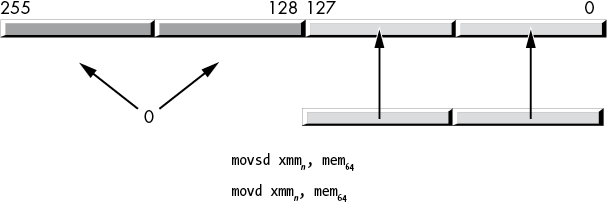
Figure 11-8: Moving a 64-bit value from memory to an XMM register (with zero extension)
The following instructions store the LO 32 or 64 bits of an XMM register into a dword or qword memory location or general-purpose register:
movd reg32/mem32, xmmn
movq reg64/mem64, xmmn
The movq instruction also allows you to copy data from the LO qword of one XMM register to another, but for whatever reason, the movd instruction does not allow two XMM register operands:
movq xmmn, xmmnFor the AVX instructions, you use the following instructions:3
vmovd xmmn, reg32/mem32
vmovd reg32/mem32, xmmn
vmovq xmmn, reg64/mem64
vmovq reg64/mem64, xmmn
The instructions with the XMM destination operands also zero-extend their values into the HO bits (up to bit 255, unlike the standard SSE instructions that do not modify the upper bits of the YMM registers).
Because the movd and movq instructions access 32- and 64-bit values in memory (rather than 128-, 256-, or 512-bit values), these instructions do not require their memory operands to be 16-, 32-, or 64-byte-aligned. Of course, the instructions may execute faster if their operands are dword (movd) or qword (movq) aligned in memory.
11.6.2 The (v)movaps, (v)movapd, and (v)movdqa Instructions
The movaps (move aligned, packed single), movapd (move aligned, packed double), and movdqa (move double quad-word aligned) instructions move 16 bytes of data between memory and an XMM register or between two XMM registers. The AVX versions (with the v prefix) move 16 or 32 bytes between memory and an XMM or a YMM register or between two XMM or YMM registers (moves involving XMM registers zero out the HO bits of the corresponding YMM register). The memory locations must be aligned on a 16-byte or 32-byte boundary (respectively), or the CPU will generate an unaligned access fault.
All three mov* instructions load 16 bytes into an XMM register and are, in theory, interchangeable. In practice, Intel may optimize the operations for the type of data they move (single-precision floating-point values, double-precision floating-point values, or integer values), so it’s always a good idea to choose the appropriate instruction for the data type you are using (see “Performance Issues and the SIMD Move Instructions” on page 622 for an explanation). Likewise, all three vmov* instructions load 16 or 32 bytes into an XMM or a YMM register and are interchangeable.
These instructions take the following forms:
movaps xmmn, mem128    vmovaps xmmn, mem128    vmovaps ymmn, mem256
movaps mem128, xmmn    vmovaps mem128, xmmn    vmovaps mem256, ymmn
movaps xmmn, xmmn     vmovaps xmmn, xmmn     vmovaps ymmn, ymmn
movapd xmmn, mem128    vmovapd xmmn, mem128    vmovapd ymmn, mem256
movapd mem128, xmmn    vmovapd mem128, xmmn    vmovapd mem256, ymmn
movapd xmmn, xmmn     vmovapd xmmn, xmmn     vmovapd ymmn, ymmn
movdqa xmmn, mem128    vmovdqa xmmn, mem128    vmovdqa ymmn, mem256
movdqa mem128, xmmn    vmovdqa mem128, xmmn    vmovdqa mem256, ymmn
movdqa xmmn, xmmn     vmovdqa xmmn, xmmn     vmovdqa ymmn, ymmn
The mem128 operand should be a vector (array) of four single-precision floating-point values for the (v)movaps instruction; it should be a vector of two double-precision floating-point values for the (v)movapd instruction; it should be a 16-byte value (16 bytes, 8 words, 4 dwords, or 2 qwords) when using the (v)movdqa instruction. If you cannot guarantee that the operands are aligned on a 16-byte boundary, use the movups, movupd, or movdqu instructions, instead (see the next section).
The mem256 operand should be a vector (array) of eight single-precision floating-point values for the vmovaps instruction; it should be a vector of four double-precision floating-point values for the vmovapd instruction; it should be a 32-byte value (32 bytes, 16 words, 8 dwords, or 4 qwords) when using the vmovdqa instruction. If you cannot guarantee that the operands are 32-byte-aligned, use the vmovups, vmovupd, or vmovdqu instructions instead.
Although the physical machine instructions themselves don’t particularly care about the data type of the memory operands, MASM’s assembly syntax certainly does care. You will need to use operand type coercion if the instruction doesn’t match one of the following types:
- The
movapsinstruction allowsreal4,dword, andowordoperands. - The
movapdinstruction allowsreal8,qword, andowordoperands. - The
movdqainstruction allows onlyowordoperands. - The
vmovapsinstruction allowsreal4,dword, andymmword ptroperands (when using a YMM register). - The
vmovapdinstruction allowsreal8,qword, andymmword ptroperands (when using a YMM register). - The
vmovdqainstruction allows onlyymmword ptroperands (when using a YMM register).
Often you will see memcpy (memory copy) functions use the (v)movapd instructions for very high-performance operations. See Agner Fog’s website at https://www.agner.org/optimize/ for more details.
11.6.3 The (v)movups, (v)movupd, and (v)movdqu Instructions
When you cannot guarantee that packed data memory operands lie on a 16- or 32-byte address boundary, you can use the (v)movups (move unaligned packed single-precision), (v)movupd (move unaligned packed double-precision), and (v)movdqu (move double quad-word unaligned) instructions to move data between XMM or YMM registers and memory.
As for the aligned moves, all the unaligned moves do the same thing: copying 16 (32) bytes of data to and from memory. The convention for the various data types is the same as it is for the aligned data movement instructions.
11.6.4 Performance of Aligned and Unaligned Moves
Listings 11-3 and 11-4 provide sample programs that demonstrate the performance of the mova* and movu* instructions using aligned and unaligned memory accesses.
; Listing 11-3

; Performance test for packed versus unpacked
; instructions. This program times aligned accesses.

        option  casemap:none

nl          =       10

            .const
ttlStr      byte    "Listing 11-3", 0

dseg        segment align(64) 'DATA'

; Aligned data types:

            align   64
alignedData byte    64 dup (0)
dseg        ends

            .code
            externdef printf:proc

; Return program title to C++ program:

            public  getTitle
getTitle    proc
            lea     rax, ttlStr
            ret
getTitle    endp

; Used for debugging:

print       proc

; Print code removed for brevity.
; See Listing 11-1 for actual code.

print       endp

; Here is the "asmMain" function.

            public  asmMain
asmMain     proc
            push    rbx
            push    rbp
            mov     rbp, rsp
            sub     rsp, 56         ; Shadow storage

            call    print
            byte    "Starting", nl, 0

            mov     rcx, 4000000000 ; 4,000,000,000
            lea     rdx, alignedData
            mov     rbx, 0
rptLp:      mov     rax, 15
rptLp2:     movaps  xmm0, xmmword ptr [rdx + rbx * 1]
            movapd  xmm0, real8 ptr   [rdx + rbx * 1]
            movdqa  xmm0, xmmword ptr [rdx + rbx * 1]
            vmovaps ymm0, ymmword ptr [rdx + rbx * 1]
            vmovapd ymm0, ymmword ptr [rdx + rbx * 1]
            vmovdqa ymm0, ymmword ptr [rdx + rbx * 1]
            vmovaps zmm0, zmmword ptr [rdx + rbx * 1]
            vmovapd zmm0, zmmword ptr [rdx + rbx * 1]

            dec     rax
            jns     rptLp2

            dec     rcx
            jnz     rptLp

            call    print
            byte    "Done", nl, 0

allDone:    leave
            pop     rbx
            ret     ; Returns to caller
asmMain     endp
            end
Listing 11-3: Aligned memory-access timing code
; Listing 11-4

; Performance test for packed versus unpacked
; instructions. This program times unaligned accesses.

        option  casemap:none

nl          =       10

            .const
ttlStr      byte    "Listing 11-4", 0

dseg        segment align(64) 'DATA'

; Aligned data types:

            align   64
alignedData byte    64 dup (0)
dseg        ends

            .code
            externdef printf:proc

; Return program title to C++ program:

            public  getTitle
getTitle    proc
            lea     rax, ttlStr
            ret
getTitle    endp

; Used for debugging:

print       proc

; Print code removed for brevity.
; See Listing 11-1 for actual code.

print       endp

; Here is the "asmMain" function.

            public  asmMain
asmMain     proc
            push    rbx
            push    rbp
            mov     rbp, rsp
            sub     rsp, 56         ; Shadow storage

            call    print
            byte    "Starting", nl, 0

            mov     rcx, 4000000000 ; 4,000,000,000
            lea     rdx, alignedData
rptLp:      mov     rbx, 15
rptLp2:
            movups  xmm0, xmmword ptr [rdx + rbx * 1]
            movupd  xmm0, real8 ptr   [rdx + rbx * 1]
            movdqu  xmm0, xmmword ptr [rdx + rbx * 1]
            vmovups ymm0, ymmword ptr [rdx + rbx * 1]
            vmovupd ymm0, ymmword ptr [rdx + rbx * 1]
            vmovdqu ymm0, ymmword ptr [rdx + rbx * 1]
            vmovups zmm0, zmmword ptr [rdx + rbx * 1]
            vmovupd zmm0, zmmword ptr [rdx + rbx * 1]
            dec     rbx
            jns     rptLp2

            dec     rcx
            jnz     rptLp

            call    print
            byte    "Done", nl, 0

allDone:    leave
            pop     rbx
            ret     ; Returns to caller
asmMain     endp
            end
Listing 11-4: Unaligned memory-access timing code
The code in Listing 11-3 took about 1 minute and 7 seconds to execute on a 3GHz Xeon W CPU. The code in Listing 11-4 took 1 minute and 55 seconds to execute on the same processor. As you can see, there is sometimes an advantage to accessing SIMD data on an aligned address boundary.
11.6.5 The (v)movlps and (v)movlpd Instructions
The (v)movl* instructions and (v)movh* instructions (from the next section) might look like normal move instructions. Their behavior is similar to many other SSE/AVX move instructions. However, they were designed to support packing and unpacking floating-point vectors. Specifically, these instructions allow you to merge two pairs of single-precision or a pair of double-precision floating-point operands from two different sources into a single XMM register.
The (v)movlps instructions use the following syntax:
movlps  xmmdest, mem64
movlps  mem64,  xmmsrc
vmovlps xmmdest, xmmsrc, mem64
vmovlps mem64,  xmmsrc
The movlps xmmdest, mem64 form copies a pair of single-precision floating-point values into the two LO 32-bit lanes of a destination XMM register, as shown in Figure 11-9. This instruction leaves the HO 64 bits unchanged.

Figure 11-9: movlps instruction
The movlps mem64, xmmsrc form copies the LO 64 bits (the two LO single-precision lanes) from the XMM source register to the specified memory location. Functionally, this is equivalent to the movq or movsd instructions (as it copies 64 bits to memory), though this instruction might be slightly faster if the LO 64 bits of the XMM register actually contain two single-precision values (see “Performance Issues and the SIMD Move Instructions” on page 622 for an explanation).
The vmovlps instruction has three operands: a destination XMM register, a source XMM register, and a source (64-bit) memory location. This instruction copies the two single-precision values from the memory location into the LO 64 bits of the destination XMM register. It copies the HO 64 bits of the source register (which also hold two single-precision values) into the HO 64 bits of the destination register. Figure 11-10 shows the operation. Note that this instruction merges the pair of operands with a single instruction.
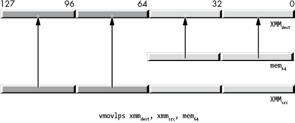
Figure 11-10: vmovlps instruction
Like movsd, the movlpd (move low packed double) instruction copies the LO 64 bits (a double-precision floating-point value) of the source operand to the LO 64 bits of the destination operand. The difference is that the movlpd instruction doesn’t zero-extend the value when moving data from memory into an XMM register, whereas the movsd instruction will zero-extend the value into the upper 64 bits of the destination XMM register. (Neither the movsd nor movlpd will zero-extend when copying data between XMM registers; of course, zero extension doesn’t apply when storing data to memory.)4
11.6.6 The movhps and movhpd Instructions
The movhps and movhpd instructions move a 64-bit value (either two single-precision floats in the case of movhps, or a single double-precision value in the case of movhpd) into the HO quad word of a destination XMM register. Figure 11-11 shows the operation of the movhps instruction; Figure 11-12 shows the movhpd instruction.

Figure 11-11: movhps instruction

Figure 11-12: movhpd instruction
The movhps and movhpd instructions can also store the HO quad word of an XMM register into memory. The allowable syntax is shown here:
movhps xmmn, mem64
movhps mem64, xmmn
movhpd xmmn, mem64
movhpd mem64, xmmn
These instructions do not affect bits 128 to 255 of the YMM registers (if present on the CPU).
You would normally use a movlps instruction followed by a movhps instruction to load four single-precision floating-point values into an XMM register, taking the floating-point values from two different data sources (similarly, you could use the movlpd and movhpd instructions to load a pair of double-precision values into a single XMM register from different sources). Conversely, you could also use this instruction to split a vector result in half and store the two halves in different data streams. This is probably the intended purpose of this instruction. Of course, if you can use it for other purposes, have at it.
MASM (version 14.15.26730.0, at least) seems to require movhps operands to be a 64-bit data type and does not allow real4 operands.5 Therefore, you may have to explicitly coerce an array of two real4 values with qword ptr when using this instruction:
r4m         real4   1.0, 2.0, 3.0, 4.0
r8m         real8   1.0, 2.0
              .
              .
              .
            movhps  xmm0, qword ptr r4m2
            movhpd  xmm0, r8m
11.6.7 The vmovhps and vmovhpd Instructions
Although the AVX instruction extensions provide vmovhps and vmovhpd instructions, they are not a simple extension of the SSE movhps and movhpd instructions. The syntax for these instructions is as follows:
vmovhps xmmdest, xmmsrc, mem64
vmovhps mem64,  xmmsrc
vmovhpd xmmdest, xmmsrc, mem64
vmovhpd mem64,  xmmsrc
The instructions that store data into a 64-bit memory location behave similarly to the movhps and movhpd instructions. The instructions that load data into an XMM register have two source operands. They load a full 128 bits (four single-precision values or two double-precision values) into the destination XMM register. The HO 64 bits come from the memory operand; the LO 64 bits come from the LO quad word of the source XMM register, as Figure 11-13 shows. These instructions also zero-extend the value into the upper 128 bits of the (overlaid) YMM register.

Figure 11-13: vmovhpd and vmovhps instructions
Unlike for the movhps instruction, MASM properly accepts real4 source operands for the vmovhps instruction:
r4m         real4   1.0, 2.0, 3.0, 4.0
r8m         real8   1.0, 2.0
              .
              .
              .
            vmovhps xmm0, xmm1, r4m
            vmovhpd xmm0, xmm1, r8m
11.6.8 The movlhps and vmovlhps Instructions
The movlhps instruction moves a pair of 32-bit single-precision floating-point values from the LO qword of the source XMM register into the HO 64 bits of a destination XMM register. It leaves the LO 64 bits of the destination register unchanged. If the destination register is on a CPU that supports 256-bit AVX registers, this instruction also leaves the HO 128 bits of the overlaid YMM register unchanged.
The syntax for these instructions is as follows:
movlhps  xmmdest, xmmsrc
vmovlhps xmmdest, xmmsrc1, xmmsrc2
You cannot use this instruction to move data between memory and an XMM register; it transfers data only between XMM registers. No double-precision version of this instruction exists.
The vmovlhps instruction is similar to movlhps, with the following differences:
vmovlhpsrequires three operands: two source XMM registers and a destination XMM register.vmovlhpscopies the LO quad word of the first source register into the LO quad word of the destination register.vmovlhpscopies the LO quad word of the second source register into bits 64 to 127 of the destination register.vmovlhpszero-extends the result into the upper 128 bits of the overlaid YMM register.
There is no vmovlhpd instruction.
11.6.9 The movhlps and vmovhlps Instructions
The movhlps instruction has the following syntax:
movhlps xmmdest, xmmsrcThe movhlps instruction copies the pair of 32-bit single-precision floating-point values from the HO qword of the source operand to the LO qword of the destination register, leaving the HO 64 bits of the destination register unchanged (this is the converse of movlhps). This instruction copies data only between XMM registers; it does not allow a memory operand.
The vmovhlps instruction requires three XMM register operands; here is its syntax:
vmovhlps xmmdest, xmmsrc1, xmmsrc2This instruction copies the HO 64 bits of the first source register into the HO 64 bits of the destination register, copies the HO 64 bits of the second source register into bits 0 to 63 of the destination register, and finally, zero-extends the result into the upper bits of the overlaid YMM register.
There are no movhlpd or vmovhlpd instructions.
11.6.10 The (v)movshdup and (v)movsldup Instructions
The movshdup instruction moves the two odd-index single-precision floating-point values from the source operand (memory or XMM register) and duplicates each element into the destination XMM register, as shown in Figure 11-14.
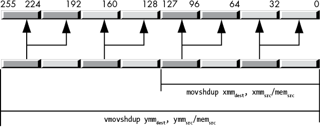
Figure 11-14: movshdup and vmovshdup instructions
This instruction ignores the single-precision floating-point values at even-lane indexes into the XMM register. The vmovshdup instruction works the same way but on YMM registers, copying four single-precision values rather than two (and, of course, zeroing the HO bits). The syntax for these instructions is shown here:
movshdup  xmmdest, mem128/xmmsrc
vmovshdup xmmdest, mem128/xmmsrc
vmovshdup ymmdest, mem256/ymmsrc
The movsldup instruction works just like the movshdup instruction, except it copies and duplicates the two single-precision values at even indexes in the source XMM register to the destination XMM register. Likewise, the vmovsldup instruction copies and duplicates the four double-precision values in the source YMM register at even indexes, as shown in Figure 11-15.
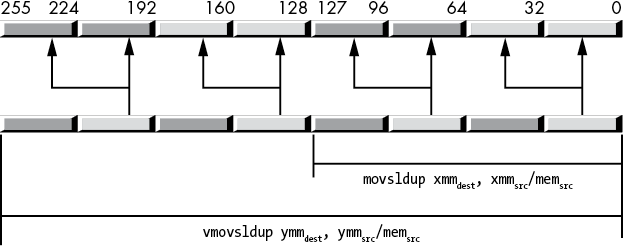
Figure 11-15: movsldup and vmovsldup instructions
The syntax is as follows:
movsldup  xmmdest, mem128/xmmsrc
vmovsldup xmmdest, mem128/xmmsrc
vmovsldup ymmdest, mem256/ymmsrc
11.6.11 The (v)movddup Instruction
The movddup instruction copies and duplicates a double-precision value from the LO 64 bits of an XMM register or a 64-bit memory location into the LO 64 bits of a destination XMM register; then it also duplicates this value into bits 64 to 127 of that same destination register, as shown in Figure 11-16.
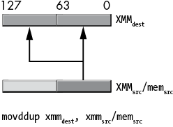
Figure 11-16: movddup instruction behavior
This instruction does not disturb the HO 128 bits of a YMM register (if applicable). The syntax for this instruction is as follows:
movddup xmmdest, mem64/xmmsrcThe vmovddup instruction operates on an XMM or a YMM destination register and an XMM or a YMM source register or 128- or 256-bit memory location. The 128-bit version works just like the movddup instruction except it zeroes the HO bits of the destination YMM register. The 256-bit version copies a pair of double-precision values at even indexes (0 and 2) in the source value to their corresponding indexes in the destination YMM register and duplicates those values at the odd indexes in the destination, as Figure 11-17 shows.
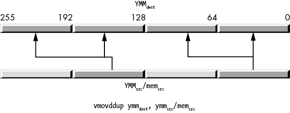
Figure 11-17: vmovddup instruction behavior
Here is the syntax for this instruction:
movddup  xmmdest, mem64/xmmsrc
vmovddup ymmdest, mem256/ymmsrc
11.6.12 The (v)lddqu Instruction
The (v)lddqu instruction is operationally identical to (v)movdqu. You can sometimes use this instruction to improve performance if the (memory) source operand is not aligned properly and crosses a cache line boundary in memory. For more details on this instruction and its performance limitations, refer to the Intel or AMD documentation (specifically, the optimization manuals).
These instructions always take the following form:
lddqu  xmmdest, mem128
vlddqu xmmdest, mem128
vlddqu ymmdest, mem256
11.6.13 Performance Issues and the SIMD Move Instructions
When you look at the SSE/AVX instructions’ semantics at the programming model level, you might question why certain instructions appear in the instruction set. For example, the movq, movsd, and movlps instructions can all load 64 bits from a memory location into the LO 64 bits of an XMM register. Why bother doing this? Why not have a single instruction that copies the 64 bits from a quad word in memory to the LO 64 bits of an XMM register (be it a 64-bit integer, a pair of 32-bit integers, a 64-bit double-precision floating-point value, or a pair of 32-bit single-precision floating-point values)? The answer lies in the term microarchitecture.
The x86-64 macroarchitecture is the programming model that a software engineer sees. In the macroarchitecture, an XMM register is a 128-bit resource that, at any given time, could hold a 128-bit array of bits (or an integer), a pair of 64-bit integer values, a pair of 64-bit double-precision floating-point values, a set of four single-precision floating-point values, a set of four double-word integers, eight words, or 16 bytes. All these data types overlay one another, just like the 8-, 16-, 32-, and 64-bit general-purpose registers overlay one another (this is known as aliasing). If you load two double-precision floating-point values into an XMM register and then modify the (integer) word at bit positions 0 to 15, you’re also changing those same bits (0 to 15) in the double-precision value in the LO qword of the XMM register. The semantics of the x86-64 programming model require this.
At the microarchitectural level, however, there is no requirement that the CPU use the same physical bits in the CPU for integer, single-precision, and double-precision values (even when they are aliased to the same register). The microarchitecture could set aside a separate set of bits to hold integers, single-precision, and double-precision values for a single register. So, for example, when you use the movq instruction to load 64 bits into an XMM register, that instruction might actually copy the bits into the underlying integer register (without affecting the single-precision or double-precision subregisters). Likewise, movlps would copy a pair of single-precision values into the single-precision register, and movsd would copy a double-precision value into the double-precision register (Figure 11-18). These separate subregisters (integer, single-precision, and double-precision) could be connected directly to the arithmetic or logical unit that handles their specific data types, making arithmetic and logical operations on those subregisters more efficient. As long as the data is sitting in the appropriate subregister, everything works smoothly.

Figure 11-18: Register aliasing at the microarchitectural level
However, what happens if you use movq to load a pair of single-precision floating-point values into an XMM register and then try to perform a single-precision vector operation on those two values? At the macroarchitectural level, the two single-precision values are sitting in the appropriate bit positions of the XMM register, so this has to be a legal operation. At the microarchitectural level, however, those two single-precision floating-point values are sitting in the integer subregister, not the single-precision subregister. The underlying microarchitecture has to note that the values are in the wrong subregister and move them to the appropriate (single-precision) subregister before performing the single-precision arithmetic or logical operation. This may introduce a slight delay (while the microarchitecture moves the data around), which is why you should always pick the appropriate move instructions for your data types.
11.6.14 Some Final Comments on the SIMD Move Instructions
The SIMD data movement instructions are a confusing bunch. Their syntax is inconsistent, many instructions duplicate the actions of other instructions, and they have some perplexing irregularity issues. Someone new to the x86-64 instruction set might ask, “Why was the instruction set designed this way?” Why, indeed?
The answer to that question is historical. The SIMD instructions did not exist on the earliest x86 CPUs. Intel added the MMX instruction set to the Pentium-series CPUs. At that time (the early 1990s), current technology allowed Intel to add only a few additional instructions, and the MMX registers were limited to 64 bits in size. Furthermore, software engineers and computer systems designers were only beginning to explore the multimedia capabilities of modern computers, so it wasn’t entirely clear which instructions (and data types) were necessary to support the type of software we see several decades later. As a result, the earliest SIMD instructions and data types were limited in scope.
As time passed, CPUs gained additional silicon resources, and software/systems engineers discovered new uses for computers (and new algorithms to run on those computers), so Intel (and AMD) responded by adding new SIMD instructions to support these more modern multimedia applications. The original MMX instructions, for example, supported only integer data types, so Intel added floating-point support in the SSE instruction set, because multimedia applications needed real data types. Then Intel extended the integer types from 64 bits to 128, 256, and even 512 bits. With each extension, Intel (and AMD) had to retain the older instruction set extensions in order to allow preexisting software to run on the new CPUs.
As a result, the newer instruction sets kept piling on new instructions that did the same work as the older ones (with some additional capabilities). This is why instructions like movaps and vmovaps have considerable overlap in their functionality. If the CPU resources had been available earlier (for example, to put 256-bit YMM registers on the CPU), there would have been almost no need for the movaps instruction—the vmovaps could have done all the work.6
In theory, we could create an architecturally elegant variant of the x86-64 by starting over from scratch and designing a minimal instruction set that handles all the activities of the current x86-64 without all the kruft and kludges present in the existing instruction set. However, such a CPU would lose the primary advantage of the x86-64: the ability to run decades of software written for the Intel architecture. The cost of being able to run all this old software is that assembly language programmers (and compiler writers) have to deal with all these irregularities in the instruction set.
11.7 The Shuffle and Unpack Instructions
The SSE/AVX shuffle and unpack instructions are variants of the move instructions. In addition to moving data around, these instructions can also rearrange the data appearing in different lanes of the XMM and YMM registers.
11.7.1 The (v)pshufb Instructions
The pshufb instruction was the first packed byte shuffle SIMD instruction (it first appeared with the MMX instruction set). Because of its origin, its syntax and behavior are a bit different from the other shuffle instructions in the instruction set. The syntax is the following:
pshufb xmmdest, xmm/mem128The first (destination) operand is an XMM register whose byte lanes pshufb will shuffle (rearrange). The second operand (either an XMM register or a 128-bit oword memory location) is an array of 16 byte values holding indexes that control the shuffle operation. If the second operand is a memory location, that oword value must be aligned on a 16-byte boundary.
Each byte (lane) in the second operand selects a value for the corresponding byte lane in the first operand, as shown in Figure 11-19.

Figure 11-19: Lane index correspondence for pshufb instruction
The 16-byte indexes in the second operand each take the form shown in Figure 11-20.

Figure 11-20: phsufb byte index
The pshufb instruction ignores bits 4 to 6 in an index byte. Bit 7 is the clear bit; if this bit contains a 1, the pshufb instruction ignores the lane index bits and stores a 0 into the corresponding byte in XMMdest. If the clear bit contains a 0, the pshufb instruction does a shuffle operation.
The pshufb shuffle operation takes place on a lane-by-lane basis. The instruction first makes a temporary copy of XMMdest. Then for each index byte (whose HO bit is 0), the pshufb copies the lane specified by the LO 4 bits of the index from the XMMdest lane that matches the index’s lane, as shown in Figure 11-21. In this example, the index appearing in lane 6 contains the value 00000011b. This selects the value in lane 3 of the temporary (original XMMdest) value and copies it to lane 6 of XMMdest. The pshufb instruction repeats this operation for all l6 lanes.
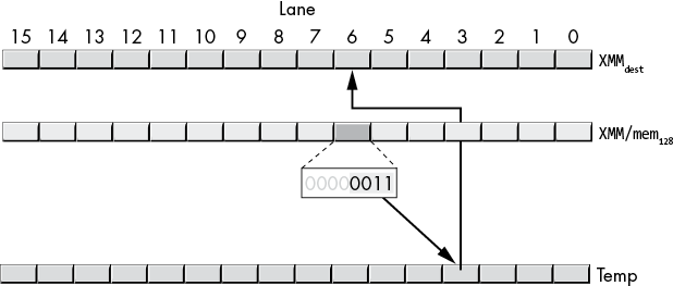
Figure 11-21: Shuffle operation
The AVX instruction set extensions introduced the vpshufb instruction. Its syntax is the following:
vpshufb xmmdest, xmmsrc, xmmindex/mem128
vpshufb ymmdest, ymmsrc, ymmindex/mem256
The AVX variant adds a source register (rather than using XMMdest as both the source and destination registers), and, rather than creating a temporary copy of XMMdest prior to the operation and picking the values from that copy, the vpshufb instructions select the source bytes from the XMMsrc register. Other than that, and the fact that these instructions zero the HO bits of YMMdest, the 128-bit variant operates identically to the SSE pshufb instruction.
The AVX instruction allows you to specify 256-bit YMM registers in addition to 128-bit XMM registers.7
11.7.2 The (v)pshufd Instructions
The SSE extensions first introduced the pshufd instruction. The AVX extensions added the vpshufd instruction. These instructions shuffle dwords in XMM and YMM registers (not double-precision values) similarly to the (v)pshufb instructions. However, the shuffle index is specified differently from (v)pshufb. The syntax for the (v)pshufd instructions is as follows:
pshufd  xmmdest, xmmsrc/mem128, imm8
vpshufd xmmdest, xmmsrc/mem128, imm8
vpshufd ymmdest, ymmsrc/mem256, imm8
The first operand (XMMdest or YMMdest) is the destination operand where the shuffled values will be stored. The second operand is the source from which the instruction will select the double words to place in the destination register; as usual, if this is a memory operand, you must align it on the appropriate (16- or 32-byte) boundary. The third operand is an 8-bit immediate value that specifies the indexes for the double words to select from the source operand.
For the (v)pshufd instructions with an XMMdest operand, the imm8 operand has the encoding shown in Table 11-3. The value in bits 0 to 1 selects a particular dword from the source operand to place in dword 0 of the XMMdest operand. The value in bits 2 to 3 selects a dword from the source operand to place in dword 1 of the XMMdest operand. The value in bits 4 to 5 selects a dword from the source operand to place in dword 2 of the XMMdest operand. Finally, the value in bits 6 to 7 selects a dword from the source operand to place in dword 3 of the XMMdest operand.
Table 11-3: (v)pshufd imm8 Operand Values
| Bit positions | Destination lane |
| 0 to 1 | 0 |
| 2 to 3 | 1 |
| 4 to 5 | 2 |
| 6 to 7 | 3 |
The difference between the 128-bit pshufd and vpshufd instructions is that pshufd leaves the HO 128 bits of the underlying YMM register unchanged and vpshufd zeroes the HO 128 bits of the underlying YMM register.
The 256-bit variant of vpshufd (when using YMM registers as the source and destination operands) still uses an 8-bit immediate operand as the index value. Each 2-bit index value manipulates two dword values in the YMM registers. Bits 0 to 1 control dwords 0 and 4, bits 2 to 3 control dwords 1 and 5, bits 4 to 5 control dwords 2 and 6, and bits 6 to 7 control dwords 3 and 7, as shown in Table 11-4.
Table 11-4: Double-Word Transfers for vpshufd YMMdest, YMMsrc/memsrc, imm8
| Index | YMM/memsrc [index] copied into | YMM/memsrc [index + 4] copied into |
| Bits 0 to 1 of imm8 | YMMdest[0] | YMMdest[4] |
| Bits 2 to 3 of imm8 | YMMdest[1] | YMMdest[5] |
| Bits 4 to 5 of imm8 | YMMdest[2] | YMMdest[6] |
| Bits 6 to 7 of imm8 | YMMdest[3] | YMMdest[7] |
The 256-bit version is slightly less flexible as it copies two dwords at a time, rather than one. It processes the LO 128 bits exactly the same way as the 128-bit version of the instruction; it also copies the corresponding lanes in the upper 128 bits of the source to the YMM destination register by using the same shuffle pattern. Unfortunately, you can’t independently control the HO and LO halves of the YMM register by using the vpshufd instruction. If you really need to shuffle dwords independently, you can use vshufb with appropriate indexes that copy 4 bytes (in place of a single dword).
11.7.3 The (v)pshuflw and (v)pshufhw Instructions
The pshuflw and vpshuflw and the pshufhw and vpshufhw instructions provide support for 16-bit word shuffles within an XMM or a YMM register. The syntax for these instructions is the following:
pshuflw  xmmdest, xmmsrc/mem128, imm8
pshufhw  xmmdest, xmmsrc/mem128, imm8

vpshuflw xmmdest, xmmsrc/mem128, imm8
vpshufhw xmmdest, xmmsrc/mem128, imm8

vpshuflw ymmdest, ymmsrc/mem256, imm8
vpshufhw ymmdest, ymmsrc/mem256, imm8
The 128-bit lw variants copy the HO 64 bits of the source operand to the same positions in the XMMdest operand. Then they use the index (imm8) operand to select word lanes 0 to 3 in the LO qword of the XMMsrc/mem128 operand to move to the LO 4 lanes of the destination operand. For example, if the LO 2 bits of imm8 are 10b, then the pshuflw instruction copies lane 2 from the source into lane 0 of the destination operand (Figure 11-22). Note that pshuflw does not modify the HO 128 bits of the overlaid YMM register, whereas vpshuflw zeroes those HO bits.
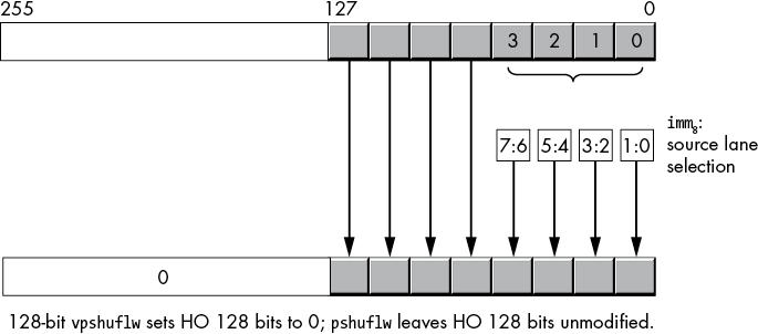
Figure 11-22: (v)pshuflw xmm, xmm/mem, imm8 operation
The 256-bit vpshuflw instruction (with a YMM destination register) copies two pairs of words at a time—one pair in the HO 128 bits and one pair in the LO 128 bits of the YMM destination register and 256-bit source locations, as shown in Figure 11-23. The index (imm8) selection is the same for the LO and HO 128 bits.
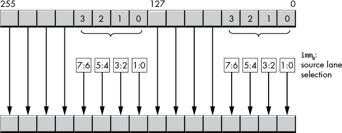
Figure 11-23: vpshuflw ymm, ymm/mem, imm8 operation
The 128-bit hw variants copy the LO 64 bits of the source operand to the same positions in the destination operand. Then they use the index operand to select words 4 to 7 (indexed as 0 to 3) in the 128-bit source operand to move to the HO four word lanes of the destination operand (Figure 11-24).
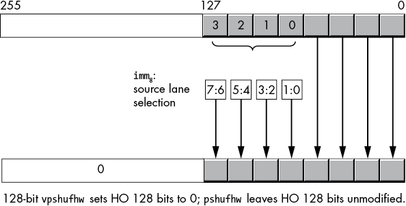
Figure 11-24: (v)pshufhw operation
The 256-bit vpshufhw instruction (with a YMM destination register) copies two pairs of words at a time—one in the HO 128 bits and one in the LO 128 bits of the YMM destination register and 256-bit source locations, as shown in Figure 11-25.
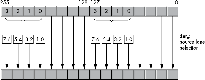
Figure 11-25: vpshufhw operation
11.7.4 The shufps and shufpd Instructions
The shuffle instructions (shufps and shufpd) extract single- or double-precision values from the source operands and place them in specified positions in the destination operand. The third operand, an 8-bit immediate value, selects which values to extract from the source to move into the destination register. The syntax for these two instructions is as follows:
shufps xmmsrc1/dest, xmmsrc2/mem128, imm8
shufpd xmmsrc1/dest, xmmsrc2/mem128, imm8
For the shufps instruction, the second source operand is an 8-bit immediate value that is actually a four-element array of 2-bit values.
imm8 bits 0 and 1 select a single-precision value from one of the four lanes in the XMMsrc1/dest operand to store into lane 0 of the destination operation. Bits 2 and 3 select a single-precision value from one of the four lanes in the XMMsrc1/dest operand to store into lane 1 of the destination operation (the destination operand is also XMMsrc1/dest).
imm8 bits 4 and 5 select a single-precision value from one of the four lanes in the XMMsrc2/memsrc2 operand to store into lane 2 of the destination operation. Bits 6 and 7 select a single-precision value from one of the four lanes in the XMMsrc2/memsrc2 operand to store into lane 3 of the destination operation.
Figure 11-26 shows the operation of the shufps instruction.
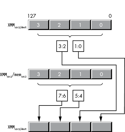
Figure 11-26: shufps operation
For example, the instruction
shufps xmm0, xmm1, 0E4h ; 0E4h = 11 10 01 00loads XMM0 with the following single-precision values:
- XMM0[0 to 31] from XMM0[0 to 32]
- XMM0[32 to 63] from XMM0[32 to 63]
- XMM0[64 to 95] from XMM1[63 to 95]
- XMM0[96 to 127] from XMM1[96 to 127]
If the second operand (XMMsrc2/memsrc2) is the same as the first operand (XMMsrc1/dest), it’s possible to rearrange the four single-precision values in the XMMdest register (which is probably the source of the instruction name shuffle).
The shufpd instruction works similarly, shuffling double-precision values. As there are only two double-precision values in an XMM register, it takes only a single bit to choose between the values. Likewise, as there are only two double-precision values in the destination register, the instruction requires only two (single-bit) array elements to choose the destination. As a result, the third operand, the imm8 value, is actually just a 2-bit value; the instruction ignores bits 2 to 7 in the imm8 operand. Bit 0 of the imm8 operand selects either lane 0 and bits 0 to 63 (if it is 0) or lane 1 and bits 64 to 127 (if it is 1) from the XMMsrc1/dest operand to place into lane 0 and bits 0 to 63 of XMMdest. Bit 1 of the imm8 operand selects either lane 0 and bits 0 to 63 (if it is 0) or lane 1 and bits 64 to 127 (if it is 1) from the XMMsrc/mem128 operand to place into lane 1 and bits 64 to 127 of XMMdest. Figure 11-27 shows this operation.
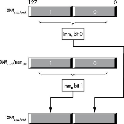
Figure 11-27: shufpd operation
11.7.5 The vshufps and vshufpd Instructions
The vshufps and vshufpd instructions are similar to shufps and shufpd. They allow you to shuffle the values in 128-bit XMM registers or 256-bit YMM registers.8 The vshufps and vshufpd instructions have four operands: a destination XMM or YMM register, two source operands (src1 must be an XMM or a YMM register, and src2 can be an XMM or a YMM register or a 128- or 256-bit memory location), and an imm8 operand. Their syntax is the following:
vshufps xmmdest, xmmsrc1, xmmsrc2/mem128, imm8
vshufpd xmmdest, xmmsrc1, xmmsrc2/mem128, imm8

vshufps ymmdest, ymmsrc1, ymmsrc2/mem256, imm8
vshufpd ymmdest, ymmsrc1, ymmsrc2/mem256, imm8
Whereas the SSE shuffle instructions use the destination register as an implicit source operand, the AVX shuffle instructions allow you to specify explicit destination and source operands (they can all be different, or all the same, or any combination thereof).
For the 256-bit vshufps instructions, the imm8 operand is an array of four 2-bit values (bits 0:1, 2:3, 4:5, and 6:7). These 2-bit values select one of four single-precision values from the source locations, as described in Table 11-5.
Table 11-5: vshufps Destination Selection
| Destination | imm8 value | ||||
| imm8 bits | 00 | 01 | 10 | 11 | |
| 76 54 32 10 | Dest[0 to 31] | Src1[0 to 31] | Src1[32 to 63] | Src1[64 to 95] | Src1[96 to 127] |
| Dest[128 to 159] | Src1[128 to 159] | Src1[160 to 191] | Src1[192 to 223] | Src1[224 to 255] | |
| 76 54 32 10 | Dest[32 to 63] | Src1[0 to 31] | Src1[32 to 63] | Src1[64 to 95] | Src1[96 to 127] |
| Dest[160 to 191] | Src1[128 to 159] | Src1[160 to 191] | Src1[192 to 223] | Src1[224 to 255] | |
| 76 54 32 10 | Dest[64 to 95] | Src2[0 to 31] | Src2[32 to 63] | Src2[64 to 95] | Src2[96 to 127] |
| Dest[192 to 223] | Src2[128 to 159] | Src2[160 to 191] | Src2[192 to 223] | Src2[224 to 255] | |
| 76 54 32 10 | Dest[96 to 127] | Src2[0 to 31] | Src2[32 to 63] | Src2[64 to 95] | Src2[96 to 127] |
| Dest[224 to 255] | Src2[128 to 159] | Src2[160 to 191] | Src2[192 to 223] | Src2[224 to 255] | |
If both source operands are the same, you can shuffle around the single-precision values in any order you choose (and if the destination and both source operands are the same, you can arbitrarily shuffle the dwords within that register).
The vshufps instruction also allows you to specify XMM and 128-bit memory operands. In this form, it behaves quite similarly to the shufps instruction except that you get to specify two different 128-bit source operands (rather than only one 128-bit source operand), and it zeroes the HO 128 bits of the corresponding YMM register. If the destination operand is different from the first source operand, this can be useful. If the vshufps’s first source operand is the same XMM register as the destination operand, you should use the shufps instruction as its machine encoding is shorter.
The vshufpd instruction is an extension of shufpd to 256 bits (plus the addition of a second source operand). As there are four double-precision values present in a 256-bit YMM register, vshufpd needs 4 bits to select the source indexes (rather than the 2 bits that shufpd requires). Table 11-6 describes how vshufpd copies the data from the source operands to the destination operand.
Table 11-6: vshufpd Destination Selection
| Destination | imm8 value | ||
| imm8 bits | 0 | 1 | |
| 7654 3 2 1 0 | Dest[0 to 63] | Src1[0 to 63] | Src1[64 to 127] |
| 7654 3 2 1 0 | Dest[64 to 127] | Src2[0 to 63] | Src2[64 to 127] |
| 7654 3 2 1 0 | Dest[128 to 191] | Src1[128 to 191] | Src1[192 to 255] |
| 7654 3 2 1 0 | Dest[192 to 255] | Src2[128 to 191] | Src2[192 to 255] |
Like the vshufps instruction, vshufpd also allows you to specify XMM registers if you want a three-operand version of shufpd.
11.7.6 The (v)unpcklps, (v)unpckhps, (v)unpcklpd, and (v)unpckhpd Instructions
The unpack (and merge) instructions are a simplified variant of the shuffle instructions. These instructions copy single- and double-precision values from fixed locations in their source operands and insert those values into fixed locations in the destination operand. They are, essentially, shuffle instructions without the imm8 operand and with fixed shuffle patterns.
The unpcklps and unpckhps instructions choose half their single-precision operands from one of two sources, merge these values (interleaving them), and then store the merged result into the destination operand (which is the same as the first source operand). The syntax for these two instructions is as follows:
unpcklps xmmdest, xmmsrc/mem128
unpckhps xmmdest, xmmsrc/mem128
The XMMdest operand serves as both the first source operand and the destination operand. The XMMsrc/mem128 operand is the second source operand.
The difference between the two is the way they select their source operands. The unpcklps instruction copies the two LO single-precision values from the source operand to bit positions 32 to 63 (dword 1) and 96 to 127 (dword 3). It leaves dword 0 in the destination operand alone and copies the value originally in dword 1 to dword 2 in the destination. Figure 11-28 diagrams this operation.
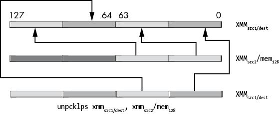
Figure 11-28: unpcklps instruction operation
The unpckhps instruction copies the two HO single-precision values from the two sources to the destination register, as shown in Figure 11-29.
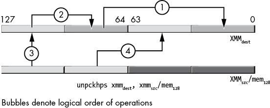
Figure 11-29: unpckhps instruction operation
The unpcklpd and unpckhpd instructions do the same thing as unpcklps and unpckhps except, of course, they operate on double-precision values rather than single-precision values. Figures 11-30 and 11-31 show the operation of these two instructions.
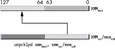
Figure 11-30: unpcklpd instruction operation
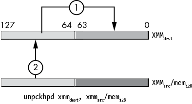
Figure 11-31: unpckhpd instruction operation
The vunpcklps, vunpckhps, vunpcklpd, and vunpckhpd instructions have the following syntax:
vunpcklps xmmdest, xmmsrc1, xmmsrc2/mem128
vunpckhps xmmdest, xmmsrc1, xmmsrc2/mem128

vunpcklps ymmdest, ymmsrc1, ymmsrc2/mem256
vunpckhps ymmdest, ymmsrc1, ymmsrc2/mem256
They work similarly to the non-v variants, with a couple of differences:
- The AVX variants support using the YMM registers as well as the XMM registers.
- The AVX variants require three operands. The first (destination) and second (source1) operands must be XMM or YMM registers. The third (source2) operand can be an XMM or a YMM register or a 128- or 256-bit memory location. The two-operand form is just a special case of the three-operand form, where the first and second operands specify the same register name.
- The 128-bit variants zero out the HO bits of the YMM register rather than leaving those bits unchanged.
Of course, the AVX instructions with the YMM registers interleave twice as many single- or double-precision values. The interleaving extension happens in the intuitive way, with vunpcklps (Figure 11-32):
- The single-precision values in source1, bits 0 to 31, are first written to bits 0 to 31 of the destination.
- The single-precision values in source2, bits 0 to 31, are written to bits 32 to 63 of the destination.
- The single-precision values in source1, bits 32 to 63, are written to bits 64 to 95 of the destination.
- The single-precision values in source2, bits 32 to 63, are written to bits 96 to 127 of the destination.
- The single-precision values in source1, bits 128 to 159, are first written to bits 128 to 159 of the destination.
- The single-precision values in source2, bits 128 to 159, are written to bits 160 to 191 of the destination.
- The single-precision values in source1, bits 160 to 191, are written to bits 192 to 223 of the destination.
- The single-precision values in source2, bits 160 to 191, are written to bits 224 to 256 of the destination.
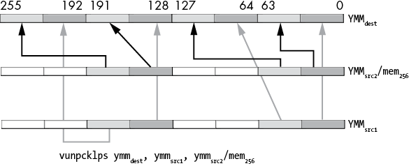
Figure 11-32: vunpcklps instruction operation
The vunpckhps instruction (Figure 11-33) does the following:
- The single-precision values in source1, bits 64 to 95, are first written to bits 0 to 31 of the destination.
- The single-precision values in source2, bits 64 to 95, are written to bits 32 to 63 of the destination.
- The single-precision values in source1, bits 96 to 127, are written to bits 64 to 95 of the destination.
- The single-precision values in source2, bits 96 to 127, are written to bits 96 to 127 of the destination.
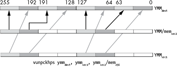
Figure 11-33: vunpckhps instruction operation
Likewise, vunpcklpd and vunpckhpd move double-precision values.
11.7.7 The Integer Unpack Instructions
The punpck* instructions provide a set of integer unpack instructions to complement the floating-point variants. These instructions appear in Table 11-7.
Table 11-7: Integer Unpack Instructions
| Instruction | Description |
punpcklbw |
Unpacks low bytes to words |
punpckhbw |
Unpacks high bytes to words |
punpcklwd |
Unpacks low words to dwords |
punpckhwd |
Unpacks high words to dwords |
punpckldq |
Unpacks low dwords to qwords |
punpckhdq |
Unpacks high dwords to qwords |
punpcklqdq |
Unpacks low qwords to owords (double qwords) |
punpckhqdq |
Unpacks high qwords to owords (double qwords) |
11.7.7.1 The punpck* Instructions
The punpck* instructions extract half the bytes, words, dwords, or qwords from two different sources and merge these values into a destination SSE register. The syntax for these instructions is shown here:
punpcklbw  xmmdest, xmmsrc
punpcklbw  xmmdest, memsrc
punpckhbw  xmmdest, xmmsrc
punpckhbw  xmmdest, memsrc
punpcklwd  xmmdest, xmmsrc
punpcklwd  xmmdest, memsrc
punpckhwd  xmmdest, xmmsrc
punpckhwd  xmmdest, memsrc
punpckldq  xmmdest, xmmsrc
punpckldq  xmmdest, memsrc
punpckhdq  xmmdest, xmmsrc
punpckhdq  xmmdest, memsrc
punpcklqdq xmmdest, xmmsrc
punpcklqdq xmmdest, memsrc
punpckhqdq xmmdest, xmmsrc
punpckhqdq xmmdest, memsrc
Figures 11- 34 through 11-41 show the data transfers for each of these instructions.
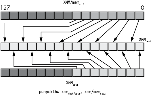
Figure 11-34: punpcklbw instruction operation
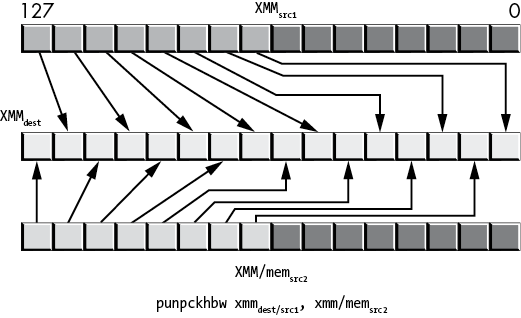
Figure 11-35: punpckhbw operation
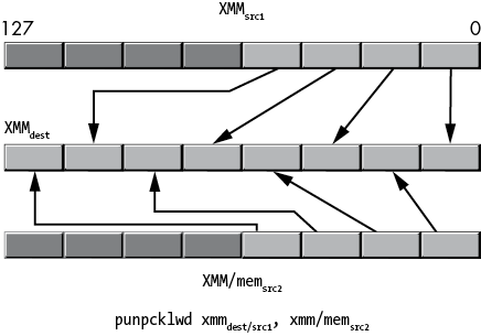
Figure 11-36: punpcklwd operation
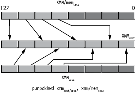
Figure 11-37: punpckhwd operation
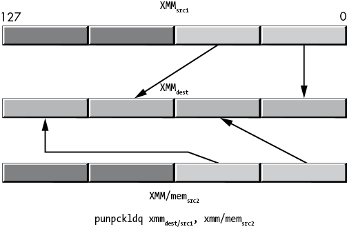
Figure 11-38: punpckldq operation
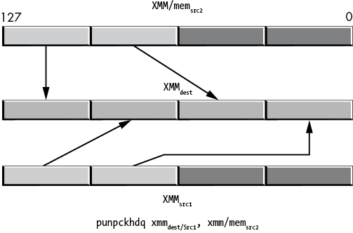
Figure 11-39: punpckhdq operation
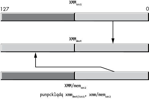
Figure 11-40: punpcklqdq operation
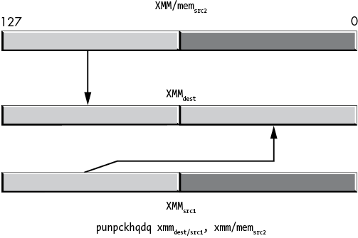
Figure 11-41: punpckhqdq operation
11.7.7.2 The vpunpck* SSE Instructions
The AVX vpunpck* instructions provide a set of AVX integer unpack instructions to complement the SSE variants. These instructions appear in Table 11-8.
Table 11-8: AVX Integer Unpack Instructions
| Instruction | Description |
vpunpcklbw |
Unpacks low bytes to words |
vpunpckhbw |
Unpacks high bytes to words |
vpunpcklwd |
Unpacks low words to dwords |
vpunpckhwd |
Unpacks high words to dwords |
vpunpckldq |
Unpacks low dwords to qwords |
vpunpckhdq |
Unpacks high dwords to qwords |
vpunpcklqdq |
Unpacks low qwords to owords (double qwords) |
vpunpckhqdq |
Unpacks high qwords to owords (double qwords) |
The vpunpck* instructions extract half the bytes, words, dwords, or qwords from two different sources and merge these values into a destination AVX or SSE register. Here is the syntax for the SSE forms of these instructions:
vpunpcklbw  xmmdest, xmmsrc1, xmmsrc2/mem128
vpunpckhbw  xmmdest, xmmsrc1, xmmsrc2/mem128
vpunpcklwd  xmmdest, xmmsrc1, xmmsrc2/mem128
vpunpckhwd  xmmdest, xmmsrc1, xmmsrc2/mem128
vpunpckldq  xmmdest, xmmsrc1, xmmsrc2/mem128
vpunpckhdq  xmmdest, xmmsrc1, xmmsrc2/mem128
vpunpcklqdq xmmdest, xmmsrc1, xmmsrc2/mem128
vpunpckhqdq xmmdest, xmmsrc1, xmmsrc2/mem128
Functionally, the only difference between these AVX instructions (vunpck*) and the SSE (unpck*) instructions is that the SSE variants leave the upper bits of the YMM AVX registers (bits 128 to 255) unchanged, whereas the AVX variants zero-extend the result to 256 bits. See Figures 11-34 through 11-41 for a description of the operation of these instructions.
11.7.7.3 The vpunpck* AVX Instructions
The AVX vunpck* instructions also support the use of the AVX YMM registers, in which case the unpack and merge operation extends from 128 bits to 256 bits. The syntax for these instructions is as follows:
vpunpcklbw  ymmdest, ymmsrc1, ymmsrc2/mem256
vpunpckhbw  ymmdest, ymmsrc1, ymmsrc2/mem256
vpunpcklwd  ymmdest, ymmsrc1, ymmsrc2/mem256
vpunpckhwd  ymmdest, ymmsrc1, ymmsrc2/mem256
vpunpckldq  ymmdest, ymmsrc1, ymmsrc2/mem256
vpunpckhdq  ymmdest, ymmsrc1, ymmsrc2/mem256
vpunpcklqdq ymmdest, ymmsrc1, ymmsrc2/mem256
vpunpckhqdq ymmdest, ymmsrc1, ymmsrc2/mem256
11.7.8 The (v)pextrb, (v)pextrw, (v)pextrd, and (v)pextrq Instructions
The (v)pextrb, (v)pextrw, (v)pextrd, and (v)pextrq instructions extract a byte, word, dword, or qword from a 128-bit XMM register and copy this data to a general-purpose register or memory location. The syntax for these instructions is the following:
pextrb  reg32, xmmsrc, imm8   ; imm8 = 0 to 15
pextrb  reg64, xmmsrc, imm8   ; imm8 = 0 to 15
pextrb  mem8, xmmsrc, imm8    ; imm8 = 0 to 15
vpextrb reg32, xmmsrc, imm8  ; imm8 = 0 to 15
vpextrb reg64, xmmsrc, imm8  ; imm8 = 0 to 15
vpextrb mem8, xmmsrc, imm8   ; imm8 = 0 to 15

pextrw  reg32, xmmsrc, imm8  ; imm8 = 0 to 7
pextrw  reg64, xmmsrc, imm8  ; imm8 = 0 to 7
pextrw  mem16, xmmsrc, imm8  ; imm8 = 0 to 7
vpextrw reg32, xmmsrc, imm8  ; imm8 = 0 to 7
vpextrw reg64, xmmsrc, imm8  ; imm8 = 0 to 7
vpextrw mem16, xmmsrc, imm8  ; imm8 = 0 to 7

pextrd  reg32, xmmsrc, imm8  ; imm8 = 0 to 3
pextrd  mem32, xmmsrc, imm8  ; imm8 = 0 to 3
vpextrd mem64, xmmsrc, imm8  ; imm8 = 0 to 3
vpextrd reg32, xmmsrc, imm8  ; imm8 = 0 to 3
vpextrd reg64, xmmsrc, imm8  ; imm8 = 0 to 3
vpextrd mem32, xmmsrc, imm8  ; imm8 = 0 to 3

pextrq  reg64, xmmsrc, imm8  ; imm8 = 0 to 1
pextrq  mem64, xmmsrc, imm8  ; imm8 = 0 to 1
vpextrq reg64, xmmsrc, imm8  ; imm8 = 0 to 1
vpextrq mem64, xmmsrc, imm8  ; imm8 = 0 to 1
The byte and word instructions expect a 32- or 64-bit general-purpose register as their destination (first operand) or a memory location that is the same size as the instruction (that is, pextrb expects a byte-sized memory operand, pextrw expects a word-sized operand, and so on). The source (second) operand is a 128-bit XMM register. The index (third) operand is an 8-bit immediate value that specifies an index (lane number). These instructions fetch the byte, word, dword, or qword in the lane specified by the 8-bit immediate value and copy that value into the destination operand. The double-word and quad-word variants require a 32-bit or 64-bit general-purpose register, respectively. If the destination operand is a 32- or 64-bit general-purpose register, the instruction zero-extends the value to 32 or 64 bits, if necessary.
11.7.9 The (v)pinsrb, (v)pinsrw, (v)pinsrd, and (v)pinsrq Instructions
The (v)pinsr{b,w,d,q} instructions take a byte, word, dword, or qword from a general-purpose register or memory location and store that data to a lane of an XMM register. The syntax for these instructions is the following:9
pinsrb  xmmdest, reg32, imm8          ; imm8 = 0 to 15
pinsrb  xmmdest, mem8, imm8           ; imm8 = 0 to 15
vpinsrb xmmdest, xmmsrc2, reg32, imm8   ; imm8 = 0 to 15
vpinsrb xmmdest, xmmsrc2, mem8, imm8    ; imm8 = 0 to 15

pinsrw  xmmdest, reg32, imm8          ; imm8 = 0 to 7
pinsrw  xmmdest, mem16, imm8          ; imm8 = 0 to 7
vpinsrw xmmdest, xmmsrc2, reg32, imm8  ; imm8 = 0 to 7
vpinsrw xmmdest, xmmsrc2, mem16, imm8  ; imm8 = 0 to 7

pinsrd  xmmdest, reg32, imm8          ; imm8 = 0 to 3
pinsrd  xmmdest, mem32, imm8          ; imm8 = 0 to 3
vpinsrd xmmdest, xmmsrc2, reg32, imm8  ; imm8 = 0 to 3
vpinsrd xmmdest, xmmsrc2, mem32, imm8  ; imm8 = 0 to 3

pinsrq  xmmdest, reg64, imm8          ; imm8 = 0 to 1
pinsrq  xmmdest, xmmsrc2, mem64, imm8  ; imm8 = 0 to 1
vpinsrq xmmdest, xmmsrc2, reg64, imm8  ; imm8 = 0 to 1
vpinsrq xmmdest, xmmsrc2, mem64, imm8  ; imm8 = 0 to 1
The destination (first) operand is a 128-bit XMM register. The pinsr* instructions expect a memory location or a 32-bit general-purpose register as their source (second) operand (except the pinsrq instructions, which require a 64-bit register). The index (third) operand is an 8-bit immediate value that specifies an index (lane number).
These instructions fetch a byte, word, dword, or qword from the general-purpose register or memory location and copy that to the lane in the XMM register specified by the 8-bit immediate value. The pinsr{b,w,d,q} instructions leave any HO bits in the underlying YMM register unchanged (if applicable).
The vpinsr{b,w,d,q} instructions copy the data from the XMM source register into the destination register and then copy the byte, word, dword, or quad word to the specified location in the destination register. These instructions zero-extend the value throughout the HO bits of the underlying YMM register.
11.7.10 The (v)extractps and (v)insertps Instructions
The extractps and vextractps instructions are functionally equivalent to pextrd and vpextrd. They extract a 32-bit (single-precision floating-point) value from an XMM register and move it into a 32-bit general-purpose register or a 32-bit memory location. The syntax for the (v)extractps instructions is shown here:
extractps  reg32, xmmsrc, imm8
extractps  mem32, xmmsrc, imm8
vextractps reg32, xmmsrc, imm8
vextractps mem32, xmmsrc, imm8
The insertps and vinsertps instructions insert a 32-bit floating-point value into an XMM register and, optionally, zero out other lanes in the XMM register. The syntax for these instructions is as follows:
insertps  xmmdest, xmmsrc, imm8
insertps  xmmdest, mem32, imm8
vinsertps xmmdest, xmmsrc1, xmmsrc2, imm8
vinsertps xmmdest, xmmsrc1, mem32, imm8
For the insertps and vinsertps instructions, the imm8 operand has the fields listed in Table 11-9.
Table 11-9: imm8 Bit Fields for insertps and vinsertps Instructions
| Bit(s) | Meaning |
| 6 to 7 | (Only if the source operand is an XMM register): Selects the 32-bit lane from the source XMM register (0, 1, 2, or 3). If the source operand is a 32-bit memory location, the instruction ignores this field and uses the full 32 bits from memory. |
| 4 to 5 | Specifies the lane in the destination XMM register in which to store the single-precision value. |
| 3 | If set, zeroes lane 3 of XMMdest. |
| 2 | If set, zeroes lane 2 of XMMdest. |
| 1 | If set, zeroes lane 1 of XMMdest. |
| 0 | If set, zeroes lane 0 of XMMdest. |
On CPUs with the AVX extensions, insertps does not modify the upper bits of the YMM registers; vinsertps zeroes the upper bits.
The vinsertps instruction first copies the XMMsrc1 register to XMMdest before performing the insertion operation. The HO bits of the corresponding YMM register are set to 0.
The x86-64 does not provide (v)extractpd or (v)insertpd instructions.
11.8 SIMD Arithmetic and Logical Operations
The SSE and AVX instruction set extensions provide a variety of scalar and vector arithmetic and logical operations.
“SSE Floating-Point Arithmetic” in Chapter 6 has already covered floating-point arithmetic using the scalar SSE instruction set, so this section does not repeat that discussion. Instead, this section covers the vector (or packed) arithmetic and logical instructions.
The vector instructions perform multiple operations in parallel on the different data lanes in an SSE or AVX register. Given two source operands, a typical SSE instruction will calculate two double-precision floating-point results, two quad-word integer calculations, four single-precision floating-point operations, four double-word integer calculations, eight word integer calculations, or sixteen byte calculations, simultaneously. The AVX registers (YMM) double the number of lanes and therefore double the number of concurrent calculations.
Figure 11-42 shows how the SSE and AVX instructions perform concurrent calculations; a value is taken from the same lane in two source locations, the calculation is performed, and the instruction stores the result to the same lane in the destination location. This process happens simultaneously for each lane in the source and destination operands. For example, if a pair of XMM registers contains four single-precision floating-point values, a SIMD packed floating-point addition instruction would add the single-precision values in the corresponding lanes of the source operands and store the single-precision sums into the corresponding lanes of the destination XMM register.
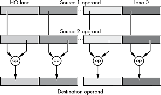
Figure 11-42: SIMD concurrent arithmetic and logical operations
Certain operations—for example, logical AND, ANDN (and not), OR, and XOR—don’t have to be broken into lanes, because those operations perform the same result regardless of the instruction size. The lane size is a single bit. Therefore, the corresponding SSE/AVX instructions operate on their entire operands without regard for a lane size.
11.9 The SIMD Logical (Bitwise) Instructions
The SSE and AVX instruction set extensions provide the logical operations shown in Table 11-10 (using C/C++ bitwise operator syntax).
Table 11-10: SSE/AVX Logical Instructions
| Operation | Description |
andpd |
dest = dest and source (128-bit operands) |
vandpd |
dest = source1 and source2 (128-bit or 256-bit operands) |
andnpd |
dest = dest and ~source (128-bit operands) |
vandnpd |
dest = source1 and ~source2 (128-bit or 256-bit operands) |
orpd |
dest = dest | source (128-bit operands) |
vorpd |
dest = source1 | source2 (128-bit or 256-bit operands) |
xorpd |
dest = dest ^ source (128-bit operands) |
vxorpd |
dest = source1 ^ source2 (128-bit or 256-bit operands) |
The syntax for these instructions is the following:
andpd   xmmdest, xmmsrc/mem128
vandpd  xmmdest, xmmsrc1, xmmsrc2/mem128
vandpd  ymmdest, ymmsrc1, ymmsrc2/mem256

andnpd  xmmdest, xmmsrc/mem128
vandnpd xmmdest, xmmsrc1, xmmsrc2/mem128
vandnpd ymmdest, ymmsrc1, ymmsrc2/mem256

orpd    xmmdest, xmmsrc/mem128
vorpd   xmmdest, xmmsrc1, xmmsrc2/mem128
vorpd   ymmdest, ymmsrc1, ymmsrc2/mem256

xorpd   xmmdest, xmmsrc/mem128
vxorpd  xmmdest, xmmsrc1, xmmsrc2/mem128
vxorpd  ymmdest, ymmsrc1, ymmsrc2/mem256
The SSE instructions (without the v prefix) leave the HO bits of the underlying YMM register unchanged (if applicable). The AVX instructions (with the v prefix) that have 128-bit operands will zero-extend their result into the HO bits of the YMM register.
If the (second) source operand is a memory location, it must be aligned on an appropriate boundary (for example, 16 bytes for mem128 values and 32 bytes for mem256 values). Failure to do so will result in a runtime memory alignment fault.
11.9.1 The (v)ptest Instructions
The ptest instruction (packed test) is similar to the standard integer test instruction. The ptest instruction performs a logical AND between the two operands and sets the zero flag if the result is 0. The ptest instruction sets the carry flag if the logical AND of the second operand with the inverted bits of the first operand produces 0. The ptest instruction supports the following syntax:
ptest  xmmsrc1, xmmsrc2/mem128
vptest xmmsrc1, xmmsrc2/mem128
vptest ymmsrc1, ymmsrc2/mem25611.9.2 The Byte Shift Instructions
The SSE and AVX instruction set extensions also support a set of logical and arithmetic shift instructions. The first two to consider are pslldq and psrldq. Although they begin with a p, suggesting they are packed (vector) instructions, these instructions really are just 128-bit logical shift-left and shift-right instructions. Their syntax is as follows:
pslldq  xmmdest, imm8
vpslldq xmmdest, xmmsrc, imm8
vpslldq ymmdest, ymmsrc, imm8
psrldq  xmmdest, imm8
vpsrldq xmmdest, xmmsrc, imm8
vpsrldq ymmdest, ymmsrc, imm8
The pslldq instruction shifts its destination XMM register to the left by the number of bytes specified by the imm8 operand. This instruction shifts 0s into the vacated LO bytes.
The vpslldq instruction takes the value in the source register (XMM or YMM), shifts that value to the left by imm8 bytes, and then stores the result into the destination register. For the 128-bit variant, this instruction zero-extends the result into bits 128 to 255 of the underlying YMM register (on AVX-capable CPUs).
The psrldq and vpsrldq instructions operate similarly to (v)pslldq except, of course, they shift their operands to the right rather than to the left. These are logical shift-right operations, so they shift 0s into the HO bytes of their operand, and bits shifted out of bit 0 are lost.
The pslldq and psrldq instructions shift bytes rather than bits. For example, many SSE instructions produce byte masks 0 or 0FFh, representing Boolean results. These instructions shift the equivalent of a bit in one of these byte masks by shifting whole bytes at a time.
11.9.3 The Bit Shift Instructions
The SSE/AVX instruction set extensions also provide vector bit shift operations that work on two or more integer lanes, concurrently. These instructions provide word, dword, and qword variants of the logical shift-left, logical shift-right, and arithmetic shift-right operations, using the syntax
shift  xmmdest, imm8
shift  xmmdest, xmmsrc/mem128
vshift xmmdest, xmmsrc, imm8
vshift xmmdest, xmmsrc, mem128
vshift ymmdest, ymmsrc, imm8
vshift ymmdest, ymmsrc, xmm/mem128
where shift = psllw, pslld, psllq, psrlw, psrld, psrlq, psraw, or psrad, and vshift = vpsllw, vpslld, vpsllq, vpsrlw, vpsrld, vpsrlq, vpsraw, vpsrad, or vpsraq.
The (v)psl* instructions shift their operands to the left; the (v)psr* instructions shift their operands to the right. The (v)psll* and (v)psrl* instructions are logical shift instructions and shift 0s into the bits vacated by the shift. Any bits shifted out of the operand are lost. The (v)psra* instructions are arithmetic shift-right instructions. They replicate the HO bit in each lane when shifting that lane’s bits to the right; all bits shifted out of the LO bit are lost.
The SSE two-operand instructions treat their first operand as both the source and destination operand. The second operand specifies the number of bits to shift (which is either an 8-bit immediate constant or a value held in an XMM register or a 128-bit memory location). Regardless of the shift count’s size, only the LO 4, 5, or 6 bits of the count are meaningful (depending on the lane size).
The AVX three-operand instructions specify a separate source and destination register for the shift operation. These instructions take the value from the source register, shift it the specified number of bits, and store the shifted result into the destination register. The source register remains unmodified (unless, of course, the instruction specifies the same register for the source and destination operands). For the AVX instructions, the source and destination registers can be XMM (128-bit) or YMM (256-bit) registers. The third operand is either an 8-bit immediate constant, an XMM register, or a 128-bit memory location. The third operand specifies the bit shift count (the same as the SSE instructions). You specify an XMM register for the count even when the source and destination registers are 256-bit YMM registers.
The w suffix instructions shift 16-bit operands (eight lanes for 128-bit destination operands, sixteen lanes for 256-bit destinations). The d suffix instructions shift 32-bit dword operands (four lanes for 128-bit destination operands, eight lanes for 256-bit destination operands). The q suffix instructions shift 64-bit operands (two lanes for 128-bit operands, four lanes for 256-bit operands).
11.10 The SIMD Integer Arithmetic Instructions
The SSE and AVX instruction set extensions deal mainly with floating-point calculations. They do, however, include a set of signed and unsigned integer arithmetic operations. This section describes the SSE/AVX integer arithmetic instructions.
11.10.1 SIMD Integer Addition
The SIMD integer addition instructions appear in Table 11-11. These instructions do not affect any flags and thus do not indicate when an overflow (signed or unsigned) occurs during the execution of these instructions. The program itself must ensure that the source operands are all within the appropriate range before performing an addition. If carry occurs during an addition, the carry is lost.
Table 11-11: SIMD Integer Addition Instructions
| Instruction | Operands | Description |
paddb |
xmmdest, xmm/mem128 | 16-lane byte addition |
vpaddb |
xmmdest, xmmsrc1, xmmsrc2/mem128 | 16-lane byte addition |
vpaddb |
ymmdest, ymmsrc1, ymmsrc2/mem256 | 32-lane byte addition |
paddw |
xmmdest, xmm/mem128 | 8-lane word addition |
vpaddw |
xmmdest, xmmsrc1, xmmsrc2/mem128 | 8-lane word addition |
vpaddw |
ymmdest, ymmsrc1, ymmsrc2/mem256 | 16-lane word addition |
paddd |
xmmdest, xmm/mem128 | 4-lane dword addition |
vpaddd |
xmmdest, xmmsrc1, xmmsrc2/mem128 | 4-lane dword addition |
vpaddd |
ymmdest, ymmsrc1, ymmsrc2/mem256 | 8-lane dword addition |
paddq |
xmmdest, xmm/mem128 | 2-lane qword addition |
vpaddq |
xmmdest, xmmsrc1, xmmsrc2/mem128 | 2-lane qword addition |
vpaddq |
ymmdest, ymmsrc1, ymmsrc2/mem256 | 4-lane qword addition |
These addition instructions are known as vertical additions because if we stack the two source operands on top of each other (on a printed page), the lane additions occur vertically (one source lane is directly above the second source lane for the corresponding addition operation).
The packed additions ignore any overflow from the addition operation, keeping only the LO byte, word, dword, or qword of each addition. As long as overflow is never possible, this is not an issue. However, for certain algorithms (especially audio and video, which commonly use packed addition), truncating away the overflow can produce bizarre results.
A cleaner solution is to use saturation arithmetic. For unsigned addition, saturation arithmetic clips (or saturates) an overflow to the largest possible value that the instruction’s size can handle. For example, if the addition of two byte values exceeds 0FFh, saturation arithmetic produces 0FFh—the largest possible unsigned 8-bit value (likewise, saturation subtraction would produce 0 if underflow occurs). For signed saturation arithmetic, clipping occurs at the largest positive and smallest negative values (for example, 7Fh/+127 for positive values and 80h/–128 for negative values).
The x86 SIMD instructions provide both signed and unsigned saturation arithmetic, though the operations are limited to 8- and 16-bit quantities.10 The instructions appear in Table 11-12.
Table 11-12: SIMD Integer Saturation Addition Instructions
| Instruction | Operands | Description |
paddsb |
xmmdest, xmm/mem128 | 16-lane byte signed saturation addition |
vpaddsb |
xmmdest, xmmsrc1, xmmsrc2/mem128 | 16-lane byte signed saturation addition |
vpaddsb |
ymmdest, ymmsrc1, ymmsrc2/mem256 | 32-lane byte signed saturation addition |
paddsw |
xmmdest, xmm/mem128 | 8-lane word signed saturation addition |
vpaddsw |
xmmdest, xmmsrc1, xmmsrc2/mem128 | 8-lane word signed saturation addition |
vpaddsw |
ymmdest, ymmsrc1, ymmsrc2/mem256 | 16-lane word signed saturation addition |
paddusb |
xmmdest, xmm/mem128 | 16-lane byte unsigned saturation addition |
vpaddusb |
xmmdest, xmmsrc1, xmmsrc2/mem128 | 16-lane byte unsigned saturation addition |
vpaddusb |
ymmdest, ymmsrc1, ymmsrc2/mem256 | 32-lane byte unsigned saturation addition |
paddusw |
xmmdest, xmm/mem128 | 8-lane word unsigned saturation addition |
vpaddusw |
xmmdest, xmmsrc1, xmmsrc2/mem128 | 8-lane word unsigned saturation addition |
vpaddusw |
ymmdest, ymmsrc1, ymmsrc2/mem256 | 16-lane word unsigned saturation addition |
As usual, both padd* and vpadd* instructions accept 128-bit XMM registers (sixteen 8-bit additions or eight 16-bit additions). The padd* instructions leave the HO bits of any corresponding YMM destination undisturbed; the vpadd* variants clear the HO bits. Also note that the padd* instructions have only two operands (the destination register is also a source), whereas the vpadd* instructions have two source operands and a single destination operand. The vpadd* instructions with the YMM register provide double the number of parallel additions.
11.10.2 Horizontal Additions
The SSE/AVX instruction sets also support three horizontal addition instructions, listed in Table 11-13.
Table 11-13: Horizontal Addition Instructions
| Instruction | Description |
(v)phaddw |
16-bit (word) horizontal add |
(v)phaddd |
32-bit (dword) horizontal add |
(v)phaddsw |
16-bit (word) horizontal add and saturate |
The horizontal addition instructions add adjacent words or dwords in their two source operands and store the sum of the result into a destination lane, as shown in Figure 11-43.
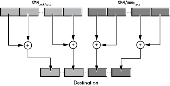
Figure 11-43: Horizontal addition operation
The phaddw instruction has the following syntax:
phaddw xmmdest, xmmsrc/mem128It computes the following:
temp[0 to 15]    = xmmdest[0 to 15]        + xmmdest[16 to 31]
temp[16 to 31]   = xmmdest[32 to 47]       + xmmdest[48 to 63]
temp[32 to 47]   = xmmdest[64 to 79]       + xmmdest[80 to 95]
temp[48 to 63]   = xmmdest[96 to 111]      + xmmdest[112 to 127]
temp[64 to 79]   = xmmsrc/mem128[0 to 15]   + xmmsrc/mem128[16 to 31]
temp[80 to 95]   = xmmsrc/mem128[32 to 47]  + xmmsrc/mem128[48 to 63]
temp[96 to 111]  = xmmsrc/mem128[64 to 79]  + xmmsrc/mem128[80 to 95]
temp[112 to 127] = xmmsrc/mem128[96 to 111] + xmmsrc/mem128[112 to 127]
xmmdest = temp
As is the case with most SSE instructions, phaddw does not affect the HO bits of the corresponding YMM destination register, only the LO 128 bits.
The 128-bit vphaddw instruction has the following syntax:
vphaddw xmmdest, xmmsrc1, xmmsrc2/mem128It computes the following:
xmmdest[0 to 15]    = xmmsrc1[0 to 15]         + xmmsrc1[16 to 31]
xmmdest[16 to 31]   = xmmsrc1[32 to 47]        + xmmsrc1[48 to 63]
xmmdest[32 to 47]   = xmmsrc1[64 to 79]        + xmmsrc1[80 to 95]
xmmdest[48 to 63]   = xmmsrc1[96 to 111]       + xmmsrc1[112 to 127]
xmmdest[64 to 79]   = xmmsrc2/mem128[0 to 15]   + xmmsrc2/mem128[16 to 31]
xmmdest[80 to 95]   = xmmsrc2/mem128[32 to 47]  + xmmsrc2/mem128[48 to 63]
xmmdest[96 to 111]  = xmmsrc2/mem128[64 to 79]  + xmmsrc2/mem128[80 to 95]
xmmdest[111 to 127] = xmmsrc2/mem128[96 to 111] + xmmsrc2/mem128[112 to 127]
The vphaddw instruction zeroes out the HO 128 bits of the corresponding YMM destination register.
The 256-bit vphaddw instruction has the following syntax:
vphaddw ymmdest, ymmsrc1, ymmsrc2/mem256vphaddw does not simply extend the 128-bit version in the intuitive way. Instead, it mixes up computations as follows (where SRC1 is YMMsrc1 and SRC2 is YMMsrc2/mem256):
ymmdest[0 to 15]    = SRC1[16 to 31]   + SRC1[0 to 15]
ymmdest[16 to 31]   = SRC1[48 to 63]   + SRC1[32 to 47]
ymmdest[32 to 47]   = SRC1[80 to 95]   + SRC1[64 to 79]
ymmdest[48 to 63]   = SRC1[112 to 127] + SRC1[96 to 111]
ymmdest[64 to 79]   = SRC2[16 to 31]   + SRC2[0 to 15]
ymmdest[80 to 95]   = SRC2[48 to 63]   + SRC2[32 to 47]
ymmdest[96 to 111]  = SRC2[80 to 95]   + SRC2[64 to 79]
ymmdest[112 to 127] = SRC2[112 to 127] + SRC2[96 to 111]
ymmdest[128 to 143] = SRC1[144 to 159] + SRC1[128 to 143]
ymmdest[144 to 159] = SRC1[176 to 191] + SRC1[160 to 175]
ymmdest[160 to 175] = SRC1[208 to 223] + SRC1[192 to 207]
ymmdest[176 to 191] = SRC1[240 to 255] + SRC1[224 to 239]
ymmdest[192 to 207] = SRC2[144 to 159] + SRC2[128 to 143]
ymmdest[208 to 223] = SRC2[176 to 191] + SRC2[160 to 175]
ymmdest[224 to 239] = SRC2[208 to 223] + SRC2[192 to 207]
ymmdest[240 to 255] = SRC2[240 to 255] + SRC2[224 to 239]
11.10.3 Double-Word–Sized Horizontal Additions
The phaddd instruction has the following syntax:
phaddd xmmdest, xmmsrc/mem128It computes the following:
temp[0 to 31]   = xmmdest[0 to 31]       + xmmdest[32 to 63]
temp[32 to 63]  = xmmdest[64 to 95]      + xmmdest[96 to 127]
temp[64 to 95]  = xmmsrc/mem128[0 to 31]  + xmmsrc/mem128[32 to 63]
temp[96 to 127] = xmmsrc/mem128[64 to 95] + xmmsrc/mem128[96 to 127]
xmmdest = temp
The 128-bit vphaddd instruction has this syntax:
vphaddd xmmdest, xmmsrc1, xmmsrc2/mem128It computes the following:
xmmdest[0 to 31]     = xmmsrc1[0 to 31]        + xmmsrc1[32 to 63]
xmmdest[32 to 63]    = xmmsrc1[64 to 95]       + xmmsrc1[96 to 127]
xmmdest[64 to 95]    = xmmsrc2/mem128[0 to 31]  + xmmsrc2/mem128[32 to 63]
xmmdest[96 to 127]   = xmmsrc2/mem128[64 to 95] + xmmsrc2/mem128[96 to 127]
(ymmdest[128 to 255] = 0)
Like vphaddw, the 256-bit vphaddd instruction has the following syntax:
vphaddd ymmdest, ymmsrc1, ymmsrc2/mem256It calculates the following:
ymmdest[0 to 31]    = ymmsrc1[32 to 63]         + ymmsrc1[0 to 31]
ymmdest[32 to 63]   = ymmsrc1[96 to 127]        + ymmsrc1[64 to 95]
ymmdest[64 to 95]   = ymmsrc2/mem128[32 to 63]   + ymmsrc2/mem128[0 to 31]
ymmdest[96 to 127]  = ymmsrc2/mem128[96 to 127]  + ymmsrc2/mem128[64 to 95]
ymmdest[128 to 159] = ymmsrc1[160 to 191]       + ymmsrc1[128 to 159]
ymmdest[160 to 191] = ymmsrc1[224 to 255]       + ymmsrc1[192 to 223]
ymmdest[192 to 223] = ymmsrc2/mem128[160 to 191] + ymmsrc2/mem128[128 to 159]
ymmdest[224 to 255] = ymmsrc2/mem128[224 to 255] + ymmsrc2/mem128[192 to 223]
If an overflow occurs during the horizontal addition, (v)phaddw and (v)phaddd simply ignore the overflow and store the LO 16 or 32 bits of the result into the destination location.
The (v)phaddsw instructions take the following forms:
phaddsw  xmmdest, xmmsrc/mem128
vphaddsw xmmdest, xmmsrc1, xmmsrc2/mem128
vphaddsw ymmdest, ymmsrc1, ymmsrc2/mem256
The (v)phaddsw instruction (horizontal signed integer add with saturate, word) is a slightly different form of (v)phaddw: rather than storing only the LO bits into the result in the destination lane, this instruction saturates the result. Saturation means that any (positive) overflow results in the value 7FFFh, regardless of the actual result. Likewise, any negative underflow results in the value 8000h.
Saturation arithmetic works well for audio and video processing. If you were using standard (wraparound/modulo) addition when adding two sound samples together, the result would be horrible clicking sounds. Saturation, on the other hand, simply produces a clipped audio signal. While this is not ideal, it sounds considerably better than the results from modulo arithmetic. Similarly, for video processing, saturation produces a washed-out (white) color versus the bizarre colors that result from modulo arithmetic.
Sadly, there is no horizontal add with saturation for double-word operands (for example, to handle 24-bit audio).
11.10.4 SIMD Integer Subtraction
The SIMD integer subtraction instructions appear in Table 11-14. As for the SIMD addition instructions, they do not affect any flags; any carry, borrow, overflow, or underflow information is lost. These instructions subtract the second source operand from the first source operand (which is also the destination operand for the SSE-only instructions) and store the result into the destination operand.
Table 11-14: SIMD Integer Subtraction Instructions
| Instruction | Operands | Description |
psubb |
xmmdest, xmm/mem128 | 16-lane byte subtraction |
vpsubb |
xmmdest, xmmsrc, xmm/mem128 | 16-lane byte subtraction |
vpsubb |
ymmdest, ymmsrc, ymm/mem256 | 32-lane byte subtraction |
psubw |
xmmdest, xmm/mem128 | 8-lane word subtraction |
vpsubw |
xmmdest, xmmsrc, xmm/mem128 | 8-lane word subtraction |
vpsubw |
ymmdest, ymmsrc, ymm/mem256 | 16-lane word subtraction |
psubd |
xmmdest, xmm/mem128 | 4-lane dword subtraction |
vpsubd |
xmmdest, xmmsrc, xmm/mem128 | 4-lane dword subtraction |
vpsubd |
ymmdest, ymmsrc, ymm/mem256 | 8-lane dword subtraction |
psubq |
xmmdest, xmm/mem128 | 2-lane qword subtraction |
vpsubq |
xmmdest, xmmsrc, xmm/mem128 | 2-lane qword subtraction |
vpsubq |
ymmdest, ymmsrc, ymm/mem256 | 4-lane qword subtraction |
The (v)phsubw, (v)phsubd, and (v)phsubsw horizontal subtraction instructions work just like the horizontal addition instructions, except (of course) they compute the difference of the two source operands rather than the sum. See the previous sections for details on the horizontal addition instructions.
Likewise, there is a set of signed and unsigned byte and word saturating subtraction instructions (see Table 11-15). For the signed instructions, the byte-sized instructions saturate positive overflow to 7Fh (+127) and negative underflow to 80h (–128). The word-sized instructions saturate to 7FFFh (+32,767) and 8000h (–32,768). The unsigned saturation instructions saturate to 0FFFFh (+65,535) and 0.
Table 11-15: SIMD Integer Saturating Subtraction Instructions
| Instruction | Operands | Description |
psubsb |
xmmdest, xmm/mem128 | 16-lane byte signed saturation subtraction |
vpsubsb |
xmmdest, xmmsrc, xmm/mem128 | 16-lane byte signed saturation subtraction |
vpsubsb |
ymmdest, ymmsrc, ymm/mem256 | 32-lane byte signed saturation subtraction |
psubsw |
xmmdest, xmm/mem128 | 8-lane word signed saturation subtraction |
vpsubsw |
xmmdest, xmmsrc, xmm/mem128 | 8-lane word signed saturation subtraction |
vpsubsw |
ymmdest, ymmsrc, ymm/mem256 | 16-lane word signed saturation subtraction |
psubusb |
xmmdest, xmm/mem128 | 16-lane byte unsigned saturation subtraction |
vpsubusb |
xmmdest, xmmsrc, xmm/mem128 | 16-lane byte unsigned saturation subtraction |
vpsubusb |
ymmdest, ymmsrc, ymm/mem256 | 32-lane byte unsigned saturation subtraction |
psubusw |
xmmdest, xmm/mem128 | 8-lane word unsigned saturation subtraction |
vpsubusw |
xmmdest, xmmsrc, xmm/mem128 | 8-lane word unsigned saturation subtraction |
vpsubusw |
ymmdest, ymmsrc, ymm/mem256 | 16-lane word unsigned saturation subtraction |
11.10.5 SIMD Integer Multiplication
The SSE/AVX instruction set extensions somewhat support multiplication. Lane-by-lane multiplication requires that the result of an operation on two n-bit values fits in n bits, but n × n multiplication can produce a 2×n-bit result. So a lane-by-lane multiplication operation creates problems as overflow is lost. The basic packed integer multiplication multiplies a pair of lanes and stores the LO bits of the result in the destination lane. For extended arithmetic, packed integer multiplication instructions produce the HO bits of the result.
The instructions in Table 11-16 handle 16-bit multiplication operations. The (v)pmullw instruction multiplies the 16-bit values appearing in the lanes of the source operand and stores the LO word of the result into the corresponding destination lane. This instruction is applicable to both signed and unsigned values. The (v)pmulhw instruction computes the product of two signed word values and stores the HO word of the result into the destination lanes. For unsigned operands, (v)pmulhuw performs the same task. By executing both (v)pmullw and (v)pmulh(u)w with the same operands, you can compute the full 32-bit result of a 16×16-bit multiplication. (You can use the punpck* instructions to merge the results into 32-bit integers.)
Table 11-16: SIMD 16-Bit Packed Integer Multiplication Instructions
| Instruction | Operands | Description |
pmullw |
xmmdest, xmm/mem128 | 8-lane word multiplication, producing the LO word of the product |
vpmullw |
xmmdest, xmmsrc, xmm/mem128 | 8-lane word multiplication, producing the LO word of the product |
vpmullw |
ymmdest, ymmsrc, ymm/mem256 | 16-lane word multiplication, producing the LO word of the product |
pmulhuw |
xmmdest, xmm/mem128 | 8-lane word unsigned multiplication, producing the HO word of the product |
vpmulhuw |
xmmdest, xmmsrc, xmm/mem128 | 8-lane word unsigned multiplication, producing the HO word of the product |
vpmulhuw |
ymmdest, ymmsrc, ymm/mem256 | 16-lane word unsigned multiplication, producing the HO word of the product |
pmulhw |
xmmdest, xmm/mem128 | 8-lane word signed multiplication, producing the HO word of the product |
vpmulhw |
xmmdest, xmmsrc, xmm/mem128 | 8-lane word signed multiplication, producing the HO word of the product |
vpmulhw |
ymmdest, ymmsrc, ymm/mem256 | 16-lane word signed multiplication, producing the HO word of the product |
Table 11-17 lists the 32- and 64-bit versions of the packed multiplication instructions. There are no (v)pmulhd or (v)pmulhq instructions; see (v)pmuludq and (v)pmuldq to handle 32- and 64-bit packed multiplication.
Table 11-17: SIMD 32- and 64-Bit Packed Integer Multiplication Instructions
| Instruction | Operands | Description |
pmulld |
xmmdest, xmm/mem128 | 4-lane dword multiplication, producing the LO dword of the product |
vpmulld |
xmmdest, xmmsrc, xmm/mem128 | 4-lane dword multiplication, producing the LO dword of the product |
vpmulld |
ymmdest, ymmsrc, ymm/mem256 | 8-lane dword multiplication, producing the LO dword of the product |
vpmullq |
xmmdest, xmmsrc, xmm/mem128 | 2-lane qword multiplication, producing the LO qword of the product |
vpmullq |
ymmdest, ymmsrc, ymm/mem256 | 4-lane qword multiplication, producing the LO qword of the product (available on only AVX-512 CPUs) |
At some point along the way, Intel introduced (v)pmuldq and (v)pmuludq to perform signed and unsigned 32×32-bit multiplications, producing a 64-bit result. The syntax for these instructions is as follows:
pmuldq   xmmdest, xmm/mem128
vpmuldq  xmmdest, xmmsrc1, xmm/mem128
vpmuldq  ymmdest, ymmsrc1, ymm/mem256

pmuludq  xmmdest, xmm/mem128
vpmuludq xmmdest, xmmsrc1, xmm/mem128
vpmuludq ymmdest, ymmsrc1, ymm/mem256
The 128-bit variants multiply the double words appearing in lanes 0 and 2 and store the 64-bit results into qword lanes 0 and 1 (dword lanes 0 and 1 and 2 and 3). On CPUs with AVX registers,11 pmuldq and pmuludq do not affect the HO 128 bits of the YMM register. The vpmuldq and vpmuludq instructions zero-extend the result to 256 bits. The 256-bit variants multiply the double words appearing in lanes 0, 2, 4, and 6, producing 64-bit results that they store in qword lanes 0, 1, 2, and 3 (dword lanes 0 and 1, 2 and 3, 4 and 5, and 6 and 7 ).
The pclmulqdq instruction provides the ability to multiply two qword values, producing a 128-bit result. Here is the syntax for this instruction:
pclmulqdq  xmmdest, xmm/mem128, imm8
vpclmulqdq xmmdest, xmmsrc1, xmmsrc2/mem128, imm8
These instructions multiply a pair of qword values found in XMMdest and XMMsrc and leave the 128-bit result in XMMdest. The imm8 operand specifies which qwords to use as the source operands. Table 11-18 lists the possible combinations for pclmulqdq. Table 11-19 lists the combinations for vpclmulqdq.
Table 11-18: imm8 Operand Values for pclmulqdq Instruction
| imm8 | Result |
| 00h | XMMdest = XMMdest[0 to 63] * XMM/mem128[0 to 63] |
| 01h | XMMdest = XMMdest[64 to 127] * XMM/mem128[0 to 63] |
| 10h | XMMdest = XMMdest[0 to 63] * XMM/mem128[64 to 127] |
| 11h | XMMdest = XMMdest[64 to 127] * XMM/mem128[64 to 127] |
Table 11-19: imm8 Operand Values for vpclmulqdq Instruction
| imm8 | Result |
| 00h | XMMdest = XMMsrc1[0 to 63] * XMMsrc2/mem128[0 to 63] |
| 01h | XMMdest = XMMsrc1[64 to 127] * XMMsrc2/mem128[0 to 63] |
| 10h | XMMdest = XMMsrc1[0 to 63] * XMMsrc2/mem128[64 to 127] |
| 11h | XMMdest = XMMsrc1[64 to 127] * XMMsrc2/mem128[64 to 127] |
As usual, pclmulqdq leaves the HO 128 bits of the corresponding YMM destination register unchanged, while vpcmulqdq zeroes those bits.
11.10.6 SIMD Integer Averages
The (v)pavgb and (v)pavgw instructions compute the average of two sets of bytes or words. These instructions sum the value in the byte or word lanes of their source and destination operands, divide the result by 2, round the results, and leave the averaged results sitting in the destination operand lanes. The syntax for these instructions is shown here:
pavgb  xmmdest, xmm/mem128
vpavgb xmmdest, xmmsrc1, xmmsrc2/mem128
vpavgb ymmdest, ymmsrc1, ymmsrc2/mem256
pavgw  xmmdest, xmm/mem128
vpavgw xmmdest, xmmsrc1, xmmsrc2/mem128
vpavgw ymmdest, ymmsrc1, ymmsrc2/mem256
The 128-bit pavgb and vpavgb instructions compute 16 byte-sized averages (for the 16 lanes in the source and destination operands). The 256-bit variant of the vpavgb instruction computes 32 byte-sized averages.
The 128-bit pavgw and vpavgw instructions compute eight word-sized averages (for the eight lanes in the source and destination operands). The 256-bit variant of the vpavgw instruction computes 16 byte-sized averages.
The vpavgb and vpavgw instructions compute the average of the first XMM or YMM source operand and the second XMM, YMM, or mem source operand, storing the average in the destination XMM or YMM register.
Unfortunately, there are no (v)pavgd or (v)pavgq instructions. No doubt, these instructions were originally intended for mixing 8- and 16-bit audio or video streams (or photo manipulation), and the x86-64 CPU designers never felt the need to extend this beyond 16 bits (even though 24-bit audio is common among professional audio engineers).
11.10.7 SIMD Integer Minimum and Maximum
The SSE4.1 instruction set extensions added eight packed integer minimum and maximum instructions, as shown in Table 11-20. These instructions scan the lanes of a pair of 128- or 256-bit operands and copy the maximum or minimum value from that lane to the same lane in the destination operand.
Table 11-20: SIMD Minimum and Maximum Instructions
| Instruction | Description |
(v)pmaxsb |
Destination byte lanes set to the maximum value of the two signed byte values found in the corresponding source lanes. |
(v)pmaxsw |
Destination word lanes set to the maximum value of the two signed word values found in the corresponding source lanes. |
(v)pmaxsd |
Destination dword lanes set to the maximum value of the two signed dword values found in the corresponding source lanes. |
vpmaxsq |
Destination qword lanes set to the maximum value of the two signed qword values found in the corresponding source lanes. (AVX-512 required for this instruction.) |
(v)pmaxub |
Destination byte lanes set to the maximum value of the two unsigned byte values found in the corresponding source lanes. |
(v)pmaxuw |
Destination word lanes set to the maximum value of the two unsigned word values found in the corresponding source lanes. |
(v)pmaxud |
Destination dword lanes set to the maximum value of the two unsigned dword values found in the corresponding source lanes. |
vpmaxuq |
Destination qword lanes set to the maximum value of the two unsigned qword values found in the corresponding source lanes. (AVX-512 required for this instruction.) |
(v)pminsb |
Destination byte lanes set to the minimum value of the two signed byte values found in the corresponding source lanes. |
(v)pminsw |
Destination word lanes set to the minimum value of the two signed word values found in the corresponding source lanes. |
(v)pminsd |
Destination dword lanes set to the minimum value of the two signed dword values found in the corresponding source lanes. |
vpminsq |
Destination qword lanes set to the minimum value of the two signed qword values found in the corresponding source lanes. (AVX-512- required for this instruction.) |
(v)pminub |
Destination byte lanes set to the minimum value of the two unsigned byte values found in the corresponding source lanes. |
(v)pminuw |
Destination word lanes set to the minimum value of the two unsigned word values found in the corresponding source lanes. |
(v)pminud |
Destination dword lanes set to the minimum value of the two unsigned dword values found in the corresponding source lanes. |
vpminuq |
Destination qword lanes set to the minimum value of the two unsigned qword values found in the corresponding source lanes. (AVX-512 required for this instruction.) |
The generic syntax for these instructions is as follows:12
pmxxyz  xmmdest, xmmsrc/mem128
vpmxxyz xmmdest, xmmsrc1, xmmsrc2/mem128
vpmxxyz ymmdest, ymmsrc1, ymmsrc2/mem256
The SSE instructions compute the minimum or maximum of the corresponding lanes in the source and destination operands and store the minimum or maximum result into the corresponding lanes in the destination register. The AVX instructions compute the minimum or maximum of the values in the same lanes of the two source operands and store the minimum or maximum result into the corresponding lanes of the destination register.
11.10.8 SIMD Integer Absolute Value
The SSE/AVX instruction set extensions provide three sets of instructions for computing the absolute values of signed byte, word, and double-word integers: (v)pabsb, (v)pabsw, and (v)pabsd.13 The syntax for these instructions is the following:
pabsb  xmmdest, xmmsrc/mem128
vpabsb xmmdest, xmmsrc/mem128
vpabsb ymmdest, ymmsrc/mem256

pabsw  xmmdest, xmmsrc/mem128
vpabsw xmmdest, xmmsrc/mem128
vpabsw ymmdest, ymmsrc/mem256

pabsd  xmmdest, xmmsrc/mem128
vpabsd xmmdest, xmmsrc/mem128
vpabsd ymmdest, ymmsrc/mem256
When operating on a system that supports AVX registers, the SSE pabsb, pabsw, and pabsd instructions leave the upper bits of the YMM registers unmodified. The 128-bit versions of the AVX instructions (vpabsb, vpabsw, and vpabsd) zero-extend the result through the upper bits.
11.10.9 SIMD Integer Sign Adjustment Instructions
The (v)psignb, (v)psignw, and (v)psignd instructions apply the sign found in a source lane to the corresponding destination lane. The algorithm works as follows:
if source lane value is less than zero then
    negate the corresponding destination lane
else if source lane value is equal to zero
    set the corresponding destination lane to zero
else
    leave the corresponding destination lane unchanged
The syntax for these instructions is the following:
psignb  xmmdest, xmmsrc/mem128
vpsignb xmmdest, xmmsrc1, xmmsrc2/mem128
vpsignb ymmdest, ymmsrc1, ymmsrc2/mem256

psignw  xmmdest, xmmsrc/mem128
vpsignw xmmdest, xmmsrc1, xmmsrc2/mem128
vpsignw ymmdest, ymmsrc1, ymmsrc2/mem256

psignd  xmmdest, xmmsrc/mem128
vpsignd xmmdest, xmmsrc1, xmmsrc2/mem128
vpsignd ymmdest, ymmsrc1, ymmsrc2/mem256
As usual, the 128-bit SSE instructions leave the upper bits of the YMM register unchanged (if applicable), and the 128-bit AVX instructions zero-extend the result into the upper bits of the YMM register.
11.10.10 SIMD Integer Comparison Instructions
The (v)pcmpeqb, (v)pcmpeqw, (v)pcmpeqd, (v)pcmpeqq, (v)pcmpgtb, (v)pcmpgtw, (v)pcmpgtd, and (v)pcmpgtq instructions provide packed signed integer comparisons. These instructions compare corresponding bytes, word, dwords, or qwords (depending on the instruction suffix) in the various lanes of their operands.14 They store the result of the comparison instruction in the corresponding destination lanes.
11.10.10.1 SSE Compare-for-Equality Instructions
The syntax for the SSE compare-for-equality instructions (pcmpeq*) is shown here:
pcmpeqb xmmdest, xmmsrc/mem128  ; Compares 16 bytes
pcmpeqw xmmdest, xmmsrc/mem128  ; Compares 8 words
pcmpeqd xmmdest, xmmsrc/mem128  ; Compares 4 dwords
pcmpeqq xmmdest, xmmsrc/mem128  ; Compares 2 qwords
These instructions compute
xmmdest[lane] = xmmdest[lane] == xmmsrc/mem128[lane]where lane varies from 0 to 15 for pcmpeqb, 0 to 7 for pcmpeqw, 0 to 3 for pcmpeqd, and 0 to 1 for pcmpeqq. The == operator produces a value of all 1 bits if the two values in the same lane are equal; it produces all 0 bits if the values are not equal.
11.10.10.2 SSE Compare-for-Greater-Than Instructions
The following is the syntax for the SSE compare-for-greater-than instructions (pcmpgt*):
pcmpgtb xmmdest, xmmsrc/mem128  ; Compares 16 bytes
pcmpgtw xmmdest, xmmsrc/mem128  ; Compares 8 words
pcmpgtd xmmdest, xmmsrc/mem128  ; Compares 4 dwords
pcmpgtq xmmdest, xmmsrc/mem128  ; Compares 2 qwords
These instructions compute
xmmdest[lane] = xmmdest[lane] > xmmsrc/mem128[lane]where lane is the same as for the compare-for-equality instructions, and the > operator produces a value of all 1 bits if the signed integer in the XMMdest lane is greater than the signed value in the corresponding XMMsrc/MEM128 lane.
On AVX-capable CPUs, the SSE packed integer comparisons preserve the value in the upper bits of the underlying YMM register.
11.10.10.3 AVX Comparison Instructions
The 128-bit variants of these instructions have the following syntax:
vpcmpeqb xmmdest, xmmsrc1, xmmsrc2/mem128  ; Compares 16 bytes
vpcmpeqw xmmdest, xmmsrc1, xmmsrc2/mem128  ; Compares 8 words
vpcmpeqd xmmdest, xmmsrc1, xmmsrc2/mem128  ; Compares 4 dwords
vpcmpeqq xmmdest, xmmsrc1, xmmsrc2/mem128  ; Compares 2 qwords

vpcmpgtb xmmdest, xmmsrc1, xmmsrc2/mem128  ; Compares 16 bytes
vpcmpgtw xmmdest, xmmsrc1, xmmsrc2/mem128  ; Compares 8 words
vpcmpgtd xmmdest, xmmsrc1, xmmsrc2/mem128  ; Compares 4 dwords
vpcmpgtq xmmdest, xmmsrc1, xmmsrc2/mem128  ; Compares 2 qwords
These instructions compute as follows:
xmmdest[lane] = xmmsrc1[lane] == xmmsrc2/mem128[lane]
xmmdest[lane] = xmmsrc1[lane] >  xmmsrc2/mem128[lane]
These AVX instructions write 0s to the upper bits of the underlying YMM register.
The 256-bit variants of these instructions have the following syntax:
vpcmpeqb ymmdest, ymmsrc1, ymmsrc2/mem256  ; Compares 32 bytes
vpcmpeqw ymmdest, ymmsrc1, ymmsrc2/mem256  ; Compares 16 words
vpcmpeqd ymmdest, ymmsrc1, ymmsrc2/mem256  ; Compares 8 dwords
vpcmpeqq ymmdest, ymmsrc1, ymmsrc2/mem256  ; Compares 4 qwords

vpcmpgtb ymmdest, ymmsrc1, ymmsrc2/mem256  ; Compares 32 bytes
vpcmpgtw ymmdest, ymmsrc1, ymmsrc2/mem256  ; Compares 16 words
vpcmpgtd ymmdest, ymmsrc1, ymmsrc2/mem256  ; Compares 8 dwords
vpcmpgtq ymmdest, ymmsrc1, ymmsrc2/mem256  ; Compares 4 qwords
These instructions compute as follows:
ymmdest[lane] = ymmsrc1[lane] == ymmsrc2/mem256[lane]
ymmdest[lane] = ymmsrc1[lane] >  ymmsrc2/mem256[lane]
Of course, the principal difference between the 256- and the 128-bit instructions is that the 256-bit variants support twice as many byte (32), word (16), dword (8), and qword (4) signed-integer lanes.
11.10.10.4 Compare-for-Less-Than Instructions
There are no packed compare-for-less-than instructions. You can synthesize a less-than comparison by reversing the operands and using a greater-than comparison. That is, if x < y, then it is also true that y > x. If both packed operands are sitting in XMM or YMM registers, swapping the registers is relatively easy (especially when using the three-operand AVX instructions). If the second operand is a memory operand, you must first load that operand into a register so you can reverse the operands (a memory operand must always be the second operand).
11.10.10.5 Using Packed Comparison Results
The question remains of what to do with the result you obtain from a packed comparison. SSE/AVX packed signed integer comparisons do not affect condition code flags (because they compare multiple values and only one of those comparisons could be moved into the flags). Instead, the packed comparisons simply produce Boolean results. You can use these results with the packed AND instructions (pand, vpand, pandn, and vpandn), the packed OR instructions (por and vpor), or the packed XOR instructions (pxor and vpxor) to mask or otherwise modify other packed data values. Of course, you could also extract the individual lane values and test them (via a conditional jump). The following section describes a straightforward way to achieve this.
11.10.10.6 The (v)pmovmskb Instructions
The (v)pmovmskb instruction extracts the HO bit from all the bytes in an XMM or YMM register and stores the 16 or 32 bits (respectively) into a general-purpose register. These instructions set all HO bits of the general-purpose register to 0 (beyond those needed to hold the mask bits). The syntax is
pmovmskb  reg, xmmsrc
vpmovmskb reg, xmmsrc
vpmovmskb reg, ymmsrc
where reg is any 32-bit or 64-bit general-purpose integer register. The semantics for the pmovmskb and vpmovmskb instructions with an XMM source register are the same, but the encoding of pmovmskb is more efficient.
The (v)pmovmskb instruction copies the sign bits from each of the byte lanes into the corresponding bit position of the general-purpose register. It copies bit 7 from the XMM register (the sign bit for lane 0) into bit 0 of the destination register; it copies bit 15 from the XMM register (the sign bit for lane 1) into bit 1 of the destination register; it copies bit 23 from the XMM register (the sign bit for lane 2) into bit 2 of the destination register; and so on.
The 128-bit instructions fill only bits 0 through 15 of the destination register (zeroing out all other bits). The 256-bit form of the vpmovmskb instruction fills bits 0 through 31 of the destination register (zeroing out HO bits if you specify a 64-bit register).
You can use the pmovmskb instruction to extract a single bit from each byte lane in an XMM or a YMM register after a (v)pcmpeqb or (v)pcmpgtb instruction. Consider the following code sequence:
pcmpeqb  xmm0, xmm1
pmovmskb eax,  xmm0
After the execution of these two instructions, EAX bit 0 will be 1 or 0 if byte 0 of XMM0 was equal, or not equal, to byte 0 of XMM1, respectively. Likewise, EAX bit 1 will contain the result of comparing byte 1 of XMM0 to XMM1, and so on for each of the following bytes (up to bit 15, which compares 16-byte values in XMM0 and XMM1).
Unfortunately, there are no pmovmskw, pmovmskd, and pmovmsq instructions. You can achieve the same result as pmovmskw by using the following code sequence:
pcmpeqw  xmm0, xmm1
pmovmskb eax, xmm0
mov      cl, 0     ; Put result here
shr      ax, 1     ; Shift out lane 7 result
rcl      cl, 1     ; Shift bit into CL
shr      ax, 1     ; Ignore this bit
shr      ax, 1     ; Shift out lane 6 result
rcl      cl, 1     ; Shift lane 6 result into CL
shr      ax, 1     ; Ignore this bit
shr      ax, 1     ; Shift out lane 5 result
rcl      cl, 1     ; Shift lane 5 result into CL
shr      ax, 1     ; Ignore this bit
shr      ax, 1     ; Shift out lane 4 result
rcl      cl, 1     ; Shift lane 4 result into CL
shr      ax, 1     ; Ignore this bit
shr      ax, 1     ; Shift out lane 3 result
rcl      cl, 1     ; Shift lane 3 result into CL
shr      ax, 1     ; Ignore this bit
shr      ax, 1     ; Shift out lane 2 result
rcl      cl, 1     ; Shift lane 2 result into CL
shr      ax, 1     ; Ignore this bit
shr      ax, 1     ; Shift out lane 1 result
rcl      cl, 1     ; Shift lane 1 result into CL
shr      ax, 1     ; Ignore this bit
shr      ax, 1     ; Shift out lane 0 result
rcl      cl, 1     ; Shift lane 0 result into CL
Because pcmpeqw produces a sequence of words (which contain either 0000h or 0FFFFh) and pmovmskb expects byte values, pmovmskb produces twice as many results as we expect, and every odd-numbered bit that pmovmskb produces is a duplicate of the preceding even-numbered bit (because the inputs are either 0000h or 0FFFFh). This code grabs every odd-numbered bit (starting with bit 15 and working down) and skips over the even-numbered bits. While this code is easy enough to follow, it is rather long and slow. If you’re willing to live with an 8-bit result for which the lane numbers don’t match the bit numbers, you can use more efficient code:
pcmpeqw  xmm0, xmm1
pmovmskb eax, xmm0
shr      al, 1     ; Move odd bits to even positions
and      al, 55h   ; Zero out the odd bits, keep even bits
and      ah, 0aah  ; Zero out the even bits, keep odd bits
or       al, ah    ; Merge the two sets of bits
This interleaves the lanes in the bit positions as shown in Figure 11-44. Usually, it’s easy enough to work around this rearrangement in the software. Of course, you can also use a 256-entry lookup table (see Chapter 10) to rearrange the bits however you desire. Of course, if you’re just going to test the individual bits rather than use them as some sort of mask, you can directly test the bits that pmovmskb leaves in EAX; you don’t have to coalesce them into a single byte.
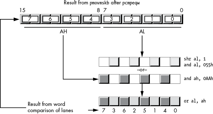
Figure 11-44: Merging bits from pcmpeqw
When using the double-word or quad-word packed comparisons, you could also use a scheme such as the one provided here for pcmpeqw. However, the floating-point mask move instructions (see “The (v)movmskps, (v)movmskpd Instructions” on page 676) do the job more efficiently by breaking the rule about using SIMD instructions that are appropriate for the data type.
11.10.11 Integer Conversions
The SSE and AVX instruction set extensions provide various instructions that convert integer values from one form to another. There are zero- and sign-extension instructions that convert from a smaller value to a larger one. Other instructions convert larger values to smaller ones. This section covers these instructions.
11.10.11.1 Packed Zero-Extension Instructions
The move with zero-extension instructions perform the conversions appearing in Table 11-21.
Table 11-21: SSE4.1 and AVX Packed Zero-Extension Instructions
| Syntax | Description |
pmovzxbw xmmdest, xmmsrc/mem64 |
Zero-extends a set of eight byte values in the LO 8 bytes of XMMsrc/mem64 to word values in XMMdest. |
pmovzxbd xmmdest, xmmsrc/mem32 |
Zero-extends a set of four byte values in the LO 4 bytes of XMMsrc/mem32 to dword values in XMMdest. |
pmovzxbq xmmdest, xmmsrc/mem16 |
Zero-extends a set of two byte values in the LO 2 bytes of XMMsrc/mem16 to qword values in XMMdest. |
pmovzxwd xmmdest, xmmsrc/mem64 |
Zero-extends a set of four word values in the LO 8 bytes of XMMsrc/mem64 to dword values in XMMdest. |
pmovzxwq xmmdest, xmmsrc/mem32 |
Zero-extends a set of two word values in the LO 4 bytes of XMMsrc/mem32 to qword values in XMMdest. |
pmovzxdq xmmdest, xmmsrc/mem64 |
Zero-extends a set of two dword values in the LO 8 bytes of XMMsrc/mem64 to qword values in XMMdest. |
A set of comparable AVX instructions also exists (same syntax, but with a v prefix on the instruction mnemonics). The difference, as usual, is that the SSE instructions leave the upper bits of the YMM register unchanged, whereas the AVX instructions store 0s into the upper bits of the YMM registers.
The AVX2 instruction set extensions double the number of lanes by allowing the use of the YMM registers. They take similar operands to the SSE/AVX instructions (substituting YMM for the destination register and doubling the size of the memory locations) and process twice the number of lanes to produce sixteen words, eight dwords, or four qwords in a YMM destination register. See Table 11-22 for details.
Table 11-22: AVX2 Packed Zero-Extension Instructions
| Syntax | Description |
vpmovzxbw ymmdest, xmmsrc/mem128 |
Zero-extends a set of sixteen byte values in the LO 16 bytes of XMMsrc/mem128 to word values in YMMdest. |
vpmovzxbd ymmdest, xmmsrc/mem64 |
Zero-extends a set of eight byte values in the LO 8 bytes of XMMsrc/mem64 to dword values in YMMdest. |
vpmovzxbq ymmdest, xmmsrc/mem32 |
Zero-extends a set of four byte values in the LO 4 bytes of XMMsrc/mem32 to qword values in YMMdest. |
vpmovzxwd ymmdest, xmmsrc/mem128 |
Zero-extends a set of eight word values in the LO 16 bytes of XMMsrc/mem128 to dword values in YMMdest. |
vpmovzxwq ymmdest, xmmsrc/mem64 |
Zero-extends a set of four word values in the LO 8 bytes of XMMsrc/mem64 to qword values in YMMdest. |
vpmovzxdq ymmdest, xmmsrc/mem128 |
Zero-extends a set of four dword values in the LO 16 bytes of XMMsrc/mem128 to qword values in YMMdest. |
11.10.11.2 Packed Sign-Extension Instructions
The SSE/AVX/AVX2 instruction set extensions provide a comparable set of instructions that sign-extend byte, word, and dword values. Table 11-23 lists the SSE packed sign-extension instructions.
Table 11-23: SSE Packed Sign-Extension Instructions
| Syntax | Description |
pmovsxbw xmmdest, xmmsrc/mem64 |
Sign-extends a set of eight byte values in the LO 8 bytes of XMMsrc/mem64 to word values in XMMdest. |
pmovsxbd xmmdest, xmmsrc/mem32 |
Sign-extends a set of four byte values in the LO 4 bytes of XMMsrc/mem32 to dword values in XMMdest. |
pmovsxbq xmmdest, xmmsrc/mem16 |
Sign-extends a set of two byte values in the LO 2 bytes of XMMsrc/mem16 to qword values in XMMdest. |
pmovsxwd xmmdest, xmmsrc/mem64 |
Sign-extends a set of four word values in the LO 8 bytes of XMMsrc/mem64 to dword values in XMMdest. |
pmovsxwq xmmdest, xmmsrc/mem32 |
Sign-extends a set of two word values in the LO 4 bytes of XMMsrc/mem32 to qword values in XMMdest. |
pmovsxdq xmmdest, xmmsrc/mem64 |
Sign-extends a set of two dword values in the LO 8 bytes of XMMsrc/mem64 to qword values in XMMdest. |
A set of corresponding AVX instructions also exists (whose mnemonics have the v prefix). As usual, the difference between the SSE and AVX instructions is that the SSE instructions leave the upper bits of the YMM register unchanged (if applicable), and the AVX instructions store 0s into those upper bits.
AVX2-capable processors also allow a YMMdest destination register, which doubles the number of (output) values the instruction can handle; see Table 11-24.
Table 11-24: AVX Packed Sign-Extension Instructions
| Syntax | Description |
vpmovsxbw ymmdest, xmmsrc/mem128 |
Sign-extends a set of sixteen byte values in the LO 16 bytes of XMMsrc/mem128 to word values in YMMdest. |
vpmovsxbd ymmdest, xmmsrc/mem64 |
Sign-extends a set of eight byte values in the LO 8 bytes of XMMsrc/mem64 to dword values in YMMdest. |
vpmovsxbq ymmdest, xmmsrc/mem32 |
Sign-extends a set of four byte values in the LO 4 bytes of XMMsrc/mem32 to qword values in YMMdest. |
vpmovsxwd ymmdest, xmmsrc/mem128 |
Sign-extends a set of eight word values in the LO 16 bytes of XMMsrc/mem128 to dword values in YMMdest. |
vpmovsxwq ymmdest, xmmsrc/mem64 |
Sign-extends a set of four word values in the LO 8 bytes of XMMsrc/mem64 to qword values in YMMdest. |
vpmovsxdq ymmdest, xmmsrc/mem128 |
Sign-extends a set of four dword values in the LO 16 bytes of XMMsrc/mem128 to qword values in YMMdest. |
11.10.11.3 Packed Sign Extension with Saturation
In addition to converting smaller signed or unsigned values to a larger format, the SSE/AVX/AVX2-capable CPUs have the ability to convert large values to smaller values via saturation; see Table 11-25.
Table 11-25: SSE Packed Sign-Extension with Saturation Instructions
| Syntax | Description |
packsswb xmmdest, xmmsrc/mem128 |
Packs sixteen signed word values (from two 128-bit sources) into sixteen byte lanes in a 128-bit destination register using signed saturation. |
packuswb xmmdest, xmmsrc/mem128 |
Packs sixteen unsigned word values (from two 128-bit sources) into sixteen byte lanes in a 128-bit destination register using unsigned saturation. |
packssdw xmmdest, xmmsrc/mem128 |
Packs eight signed dword values (from two 128-bit sources) into eight word values in a 128-bit destination register using signed saturation. |
packusdw xmmdest, xmmsrc/mem128 |
Packs eight unsigned dword values (from two 128-bit sources) into eight word values in a 128-bit destination register using unsigned saturation. |
The saturate operation checks its operand to see if the value exceeds the range of the result (–128 to +127 for signed bytes, 0 to 255 for unsigned bytes, –32,768 to +32,767 for signed words, and 0 to 65,535 for unsigned words). When saturating to a byte, if the signed source value is less than –128, byte saturation sets the value to –128. When saturating to a word, if the signed source value is less than –32,786, signed saturation sets the value to –32,768. Similarly, if a signed byte or word value exceeds +127 or +32,767, then saturation replaces the value with +127 or +32,767, respectively. For unsigned operations, saturation limits the value to +255 (for bytes) or +65,535 (for words). Unsigned values are never less than 0, so unsigned saturation clips values to only +255 or +65,535.
AVX-capable CPUs provide 128-bit variants of these instructions that support three operands: two source operands and an independent destination operand. These instructions (mnemonics the same as the SSE instructions, with a v prefix) have the following syntax:
vpacksswb  xmmdest, xmmsrc1, xmmsrc2/mem128
vpackuswb  xmmdest, xmmsrc1, xmmsrc2/mem128
vpackssdw  xmmdest, xmmsrc1, xmmsrc2/mem128
vpackusdw  xmmdest, xmmsrc1, xmmsrc2/mem128
These instructions are roughly equivalent to the SSE variants, except that these instructions use XMMsrc1 as the first source operand rather than XMMdest (which the SSE instructions use). Also, the SSE instructions do not modify the upper bits of the YMM register (if present on the CPU), whereas the AVX instructions store 0s into the upper YMM register bits.
AVX2-capable CPUs also allow the use of the YMM registers (and 256-bit memory locations) to double the number of values the instruction can saturate (see Table 11-26). Of course, don’t forget to check for AVX2 (and AVX) compatibility before using these instructions.
Table 11-26: AVX Packed Sign-Extension with Saturation Instructions
| Syntax | Description |
vpacksswb ymmdest, ymmsrc1, ymmsrc2/mem256 |
Packs 32 signed word values (from two 256-bit sources) into 32 byte lanes in a 256-bit destination register using signed saturation. |
vpackuswb ymmdest, ymmsrc1, ymmsrc2/mem256 |
Packs 32 unsigned word values (from two 256-bit sources) into 32 byte lanes in a 256-bit destination register using unsigned saturation. |
vpackssdw ymmdest, ymmsrc1, ymmsrc2/mem256 |
Packs 16 signed dword values (from two 256-bit sources) into 16 word values in a 256-bit destination register using signed saturation. |
vpackusdw ymmdest, ymmsrc1, ymmsrc2/mem256 |
Packs 16 unsigned dword values (from two 256-bit sources) into 16 word values in a 256-bit destination register using unsigned saturation. |
11.11 SIMD Floating-Point Arithmetic Operations
The SSE and AVX instruction set extensions provide packed arithmetic equivalents for all the scalar floating-point instructions in “SSE Floating-Point Arithmetic” in Chapter 6. This section does not repeat the discussion of the scalar floating-point operations; see Chapter 6 for more details.
The 128-bit SSE packed floating-point instructions have the following generic syntax (where instr is one of the floating-point instructions in Table 11-27):
instrps xmmdest, xmmsrc/mem128
instrpd xmmdest, xmmsrc/mem128
The packed single (*ps) instructions perform four single-precision floating-point operations simultaneously. The packed double (*pd) instructions perform two double-precision floating-point operations simultaneously. As is typical for SSE instructions, these packed arithmetic instructions compute
xmmdest[lane] = xmmdest[lane] op xmmsrc/mem128[lane]where lane varies from 0 to 3 for packed single-precision instructions and from 0 to 1 for packed double-precision instructions. op represents the operation (such as addition or subtraction). When the SSE instructions are executed on a CPU that supports the AVX extensions, the SSE instructions leave the upper bits of the AVX register unmodified.
The 128-bit AVX packed floating-point instructions have this syntax:15
vinstrps xmmdest, xmmsrc1, xmmsrc2/mem128 ; For dyadic operations
vinstrpd xmmdest, xmmsrc1, xmmsrc2/mem128 ; For dyadic operations
vinstrps xmmdest, xmmsrc/mem128          ; For monadic operations
vinstrpd xmmdest, xmmsrc/mem128          ; For monadic operations
These instructions compute
xmmdest[lane] = xmmsrc1[lane] op xmmsrc2/mem128[lane]where op corresponds to the operation associated with the specific instruction (for example, vaddps does a packed single-precision addition). These 128-bit AVX instructions clear the HO bits of the underlying YMMdest register.
The 256-bit AVX packed floating-point instructions have this syntax:
vinstrps ymmdest, ymmsrc1, ymmsrc2/mem256 ; For dyadic operations
vinstrpd ymmdest, ymmsrc1, ymmsrc2/mem256 ; For dyadic operations
vinstrps ymmdest, ymmsrc/mem256          ; For monadic operations
vinstrpd ymmdest, ymmsrc/mem256          ; For monadic operations
These instructions compute
ymmdest[lane] = ymmsrc1[lane] op ymmsrc/mem256[lane]where op corresponds to the operation associated with the specific instruction (for example, vaddps is a packed single-precision addition). Because these instructions operate on 256-bit operands, they compute twice as many lanes of data as the 128-bit instructions. Specifically, they simultaneously compute eight single-precision (the v*ps instructions) or four double-precision results (the v*pd instructions).
Table 11-27 provides the list of SSE/AVX packed instructions.
Table 11-27: Floating-Point Arithmetic Instructions
| Instruction | Lanes | Description |
addps |
4 | Adds four single-precision floating-point values |
addpd |
2 | Adds two double-precision floating-point values |
vaddps |
4/8 | Adds four (128-bit/XMM operands) or eight (256-bit/YMM operands) single-precision values |
vaddpd |
2/4 | Adds two (128-bit/XMM operands) or four (256-bit/YMM operands) double-precision values |
subps |
4 | Subtracts four single-precision floating-point values |
subpd |
2 | Subtracts two double-precision floating-point values |
vsubps |
4/8 | Subtracts four (128-bit/XMM operands) or eight (256-bit/YMM operands) single-precision values |
vsubpd |
2/4 | Subtracts two (128-bit/XMM operands) or four (256-bit/YMM operands) double-precision values |
mulps |
4 | Multiplies four single-precision floating-point values |
mulpd |
2 | Multiplies two double-precision floating-point values |
vmulps |
4/8 | Multiplies four (128-bit/XMM operands) or eight (256-bit/YMM operands) single-precision values |
vmulpd |
2/4 | Multiplies two (128-bit/XMM operands) or four (256-bit/YMM operands) double-precision values |
divps |
4 | Divides four single-precision floating-point values |
divpd |
2 | Divides two double-precision floating-point values |
vdivps |
4/8 | Divides four (128-bit/XMM operands) or eight (256-bit/YMM operands) single-precision values |
vdivpd |
2/4 | Divides two (128-bit/XMM operands) or four (256-bit/YMM operands) double-precision values |
maxps |
4 | Computes the maximum of four pairs of single-precision floating-point values |
maxpd |
2 | Computes the maximum of two pairs of double-precision floating-point values |
vmaxps |
4/8 | Computes the maximum of four (128-bit/XMM operands) or eight (256-bit/YMM operands) pairs of single-precision values |
vmaxpd |
2/4 | Computes the maximum of two (128-bit/XMM operands) or four (256-bit/YMM operands) pairs of double-precision values |
minps |
4 | Computes the minimum of four pairs of single-precision floating-point values |
minpd |
2 | Computes the minimum of two pairs of double-precision floating-point values |
vminps |
4/8 | Computes the minimum of four (128-bit/XMM operands) or eight (256-bit/YMM operands) pairs of single-precision values |
vminpd |
2/4 | Computes the minimum of two (128-bit/XMM operands) or four (256-bit/YMM operands) pairs of double-precision values |
sqrtps |
4 | Computes the square root of four single-precision floating-point values |
sqrtpd |
2 | Computes the square root of two double-precision floating-point values |
vsqrtps |
4/8 | Computes the square root of four (128-bit/XMM operands) or eight (256-bit/YMM operands) single-precision values |
vsqrtpd |
2/4 | Computes the square root of two (128-bit/XMM operands) or four (256-bit/YMM operands) double-precision values |
rsqrtps |
4 | Computes the approximate reciprocal square root of four single-precision floating-point values* |
vrsqrtps |
4/8 | Computes the approximate reciprocal square root of four (128-bit/XMM operands) or eight (256-bit/YMM operands) single-precision values |
* The relative error is ≤ 1.5 × 2-12. |
||
The SSE/AVX instruction set extensions also include floating-point horizontal addition and subtraction instructions. The syntax for these instructions is as follows:
haddps  xmmdest, xmmsrc/mem128
vhaddps xmmdest, xmmsrc1, xmmsrc2/mem128
vhaddps ymmdest, ymmsrc1, ymmsrc2/mem256
haddpd  xmmdest, xmmsrc/mem128
vhaddpd xmmdest, xmmsrc1, xmmsrc2/mem128
vhaddpd ymmdest, ymmsrc1, ymmsrc2/mem256

hsubps  xmmdest, xmmsrc/mem128
vhsubps xmmdest, xmmsrc1, xmmsrc2/mem128
vhsubps ymmdest, ymmsrc1, ymmsrc2/mem256
hsubpd  xmmdest, xmmsrc/mem128
vhsubpd xmmdest, xmmsrc1, xmmsrc2/mem128
vhsubpd ymmdest, ymmsrc1, ymmsrc2/mem256
As for the integer horizontal addition and subtraction instructions, these instructions add or subtract the values in adjacent lanes in the same register and store the result in the destination register (lane 2), as shown in Figure 11-43.
11.12 SIMD Floating-Point Comparison Instructions
Like the integer packed comparisons, the SSE/AVX floating-point comparisons compare two sets of floating-point values (either single- or double-precision, depending on the instruction’s syntax) and store a resulting Boolean value (all 1 bits for true, all 0 bits for false) into the destination lane. However, the floating-point comparisons are far more comprehensive than those of their integer counterparts. Part of the reason is that floating-point arithmetic is more complex; however, an ever-increasing silicon budget for the CPU designers is also responsible for this.
11.12.1 SSE and AVX Comparisons
There are two sets of basic floating-point comparisons: (v)cmpps, which compares a set of packed single-precision values, and (v)cmppd, which compares a set of packed double-precision values. Instead of encoding the comparison type into the mnemonic, these instructions use an imm8 operand whose value specifies the type of comparison. The generic syntax for these instructions is as follows:
cmpps  xmmdest, xmmsrc/mem128, imm8
vcmpps xmmdest, xmmsrc1, xmmsrc2/mem128, imm8
vcmpps ymmdest, ymmsrc1, ymmsrc2/mem256, imm8

cmppd  xmmdest, xmmsrc/mem128, imm8
vcmppd xmmdest, xmmsrc1, xmmsrc2/mem128, imm8
vcmppd ymmdest, ymmsrc1, ymmsrc2/mem256, imm8
The imm8 operand specifies the type of the comparison. There are 32 possible comparisons, as listed in Table 11-28.
Table 11-28: imm8 Values for cmpps and cmppd Instructions†
| imm8 | Description | Result | Signal | |||
| A < B | A = B | A > B | Unord | |||
| 00h | EQ, ordered, quiet | 0 | 1 | 0 | 0 | No |
| 01h | LT, ordered, signaling | 1 | 0 | 0 | 0 | Yes |
| 02h | LE, ordered, signaling | 1 | 1 | 0 | 0 | Yes |
| 03h | Unordered, quiet | 0 | 0 | 0 | 1 | No |
| 04h | NE, unordered, quiet | 1 | 0 | 1 | 1 | No |
| 05h | NLT, unordered, signaling | 0 | 1 | 1 | 1 | Yes |
| 06h | NLE, unordered, signaling | 0 | 0 | 1 | 1 | Yes |
| 07h | Ordered, quiet | 1 | 1 | 1 | 0 | No |
| 08h | EQ, unordered, quiet | 0 | 1 | 0 | 1 | No |
| 09h | NGE, unordered, signaling | 1 | 0 | 0 | 1 | Yes |
| 0Ah | NGT, unordered, signaling | 1 | 1 | 0 | 1 | Yes |
| 0Bh | False, ordered, quiet | 0 | 0 | 0 | 0 | No |
| 0Ch | NE, ordered, quiet | 1 | 0 | 1 | 0 | No |
| 0Dh | GE, ordered, signaling | 0 | 1 | 1 | 0 | Yes |
| 0Eh | GT, ordered, signaling | 0 | 0 | 1 | 0 | Yes |
| 0Fh | True, unordered, quiet | 1 | 1 | 1 | 1 | No |
| 10h | EQ, ordered, signaling | 0 | 1 | 0 | 0 | Yes |
| 11h | LT, ordered, quiet | 1 | 0 | 0 | 0 | No |
| 12h | LE, ordered, quiet | 1 | 1 | 0 | 0 | No |
| 13h | Unordered, signaling | 0 | 0 | 0 | 1 | Yes |
| 14h | NE, unordered, signaling | 1 | 0 | 1 | 1 | Yes |
| 15h | NLT, unordered, quiet | 0 | 1 | 1 | 1 | No |
| 16h | NLE, unordered, quiet | 0 | 0 | 1 | 1 | No |
| 17h | Ordered, signaling | 1 | 1 | 1 | 0 | Yes |
| 18h | EQ, unordered, signaling | 0 | 1 | 0 | 1 | Yes |
| 19h | NGE, unordered, quiet | 1 | 0 | 0 | 1 | No |
| 1Ah | NGT, unordered, quiet | 1 | 1 | 0 | 1 | No |
| 1Bh | False, ordered, signaling | 0 | 0 | 0 | 0 | Yes |
| 1Ch | NE, ordered, signaling | 1 | 0 | 1 | 0 | Yes |
| 1Dh | GE, ordered, quiet | 0 | 1 | 1 | 0 | No |
| 1Eh | GT, ordered, quiet | 0 | 0 | 1 | 0 | No |
| 1Fh | True, unordered, signaling | 1 | 1 | 1 | 1 | Yes |
† The darker shaded entries are available only on CPUs that support AVX extensions. |
||||||
The “true” and “false” comparisons always store true or false into the destination lanes. For the most part, these comparisons aren’t particularly useful. The pxor, xorps, xorpd, vxorps, and vxorpd instructions are probably better for setting an XMM or a YMM register to 0. Prior to AVX2, using a true comparison was the shortest instruction that would set all bits in an XMM or a YMM register to 1, though pcmpeqb is commonly used as well (be aware of microarchitectural inefficiencies with this latter instruction).
Note that non-AVX CPUs do not implement the GT, GE, NGT, and NGE instructions. On these CPUs, use the inverse operation (for example, NLT for GE) or swap the operands and use the opposite condition (as was done for the packed integer comparisons).
11.12.2 Unordered vs. Ordered Comparisons
The unordered relationship is true when at least one of the two source operands being compared is a NaN; the ordered relationship is true when neither source operand is a NaN. Having ordered and unordered comparisons allows you to pass error conditions through comparisons as false or true, depending on how you interpret the final Boolean results appearing in the lanes. Unordered results, as their name implies, are incomparable. When you compare two values, one of which is not a number, you must always treat the result as a failed comparison.
To handle this situation, you use an ordered or unordered comparison to force the result to be false or true, the opposite of what you ultimately expect when using the comparison result. For example, suppose you are comparing a sequence of values and want the resulting masks to be true if all the comparisons are valid (for example, you’re testing to see if all the src1 values are greater than the corresponding src2 values). You would use an ordered comparison in this situation that would force a particular lane to false if one of the values being compared is NaN. On the other hand, if you’re checking to see if all the conditions are false after the comparison, you’d use an unordered comparison to force the result to true if any of the values are NaN.
11.12.3 Signaling and Quiet Comparisons
The signaling comparisons generate an invalid arithmetic operation exception (IA) when an operation produces a quiet NaN. The quiet comparisons do not throw an exception and reflect only the status in the MXCSR (see “SSE MXCSR Register” in Chapter 6). Note that you can also mask signaling exceptions in the MXCSR register; you must explicitly set the IM (invalid operation mask, bit 7) in the MXCSR to 0 if you want to allow exceptions.
11.12.4 Instruction Synonyms
MASM supports the use of certain synonyms so you don’t have to memorize the 32 encodings. Table 11-29 lists these synonyms. In this table, x1 denotes the destination operand (XMMn or YMMn), and x2 denotes the source operand (XMMn/mem128 or YMMn/mem256, as appropriate).
Table 11-29: Synonyms for Common Packed Floating-Point Comparisons
| Synonym | Instruction | Synonym | Instruction |
cmpeqps x1, x2 |
cmpps x1, x2, 0 |
cmpeqpd x1, x2 |
cmppd x1, x2, 0 |
cmpltps x1, x2 |
cmpps x1, x2, 1 |
cmpltpd x1, x2 |
cmppd x1, x2, 1 |
cmpleps x1, x2 |
cmpps x1, x2, 2 |
cmplepd x1, x2 |
cmppd x1, x2, 2 |
cmpunordps x1, x2 |
cmpps x1, x2, 3 |
cmpunordpd x1, x2 |
cmppd x1, x2, 3 |
cmpneqps x1, x2 |
cmpps x1, x2, 4 |
cmpneqpd x1, x2 |
cmppd x1, x2, 4 |
cmpnltps x1, x2 |
cmpps x1, x2, 5 |
cmpnltpd x1, x2 |
cmppd x1, x2, 5 |
cmpnleps x1, x2 |
cmpps x1, x2, 6 |
cmpnlepd x1, x2 |
cmppd x1, x2, 6 |
cmpordps x1, x2 |
cmpps x1, x2, 7 |
cmpordpd x1, x2 |
cmppd x1, x2, 7 |
The synonyms allow you to write instructions such as
cmpeqps xmm0, xmm1rather than
cmpps xmm0, xmm1, 0 ; Compare xmm0 to xmm1 for equalityObviously, using the synonym makes the code much easier to read and understand. There aren’t synonyms for all the possible comparisons. To create readable synonyms for the instructions MASM doesn’t support, you can use a macro (or a more readable symbolic constant). For more information on macros, see Chapter 13.
11.12.5 AVX Extended Comparisons
The AVX versions of these instructions allow three register operands: a destination XMM or YMM register, a source XMM or YMM register, and a source XMM or YMM register or 128-bit or 256-bit memory location (followed by the imm8 operand specifying the type of the comparison). The basic syntax is the following:
vcmpps xmmdest, xmmsrc1, xmmsrc2/mem128, imm8
vcmpps ymmdest, ymmsrc1, ymmsrc2/mem256, imm8

vcmppd xmmdest, xmmsrc1, xmmsrc2/mem128, imm8
vcmppd ymmdest, ymmsrc1, ymmsrc2/mem256, imm8
The 128-bit vcmpps instruction compares the four single-precision floating-point values in each lane of the XMMsrc1 register against the values in the corresponding XMMsrc2/mem128 lanes and stores the true (all 1 bits) or false (all 0 bits) result into the corresponding lane of the XMMdest register. The 256-bit vcmpps instruction compares the eight single-precision floating-point values in each lane of the YMMsrc1 register against the values in the corresponding YMMsrc2/mem256 lanes and stores the true or false result into the corresponding lane of the YMMdest register.
The vcmppd instructions compare the double-precision values in the two lanes (128-bit version) or four lanes (256-bit version) and store the result into the corresponding lane of the destination register.
As for the SSE compare instructions, the AVX instructions provide synonyms that eliminate the need to memorize 32 imm8 values. Table 11-30 lists the 32 instruction synonyms.
Table 11-30: AVX Packed Compare Instructions
| imm8 | Instruction |
| 00h | vcmpeqps or vcmpeqpd |
| 01h | vcmpltps or vcmpltpd |
| 02h | vcmpleps or vcmplepd |
| 03h | vcmpunordps or vcmpunordpd |
| 04h | vcmpneqps or vcmpneqpd |
| 05h | vcmpltps or vcmpltpd |
| 06h | vcmpleps or vcmplepd |
| 07h | vcmpordps or vcmpordpd |
| 08h | vcmpeq_uqps or vcmpeq_uqpd |
| 09h | vcmpngeps or vcmpngepd |
| 0Ah | vcmpngtps or vcmpngtpd |
| 0Bh | vcmpfalseps or vcmpfalsepd |
| 0Ch | vcmpneq_oqps or vcmpneq_oqpd |
| 0Dh | vcmpgeps or vcmpgepd |
| 0Eh | vcmpgtps or vcmpgtpd |
| 0Fh | vcmptrueps or vcmptruepd |
| 10h | vcmpeq_osps or vcmpeq_ospd |
| 11h | vcmplt_oqps or vcmplt_oqpd |
| 12h | vcmple_oqps or vcmple_oqpd |
| 13h | vcmpunord_sps or vcmpunord_spd |
| 14h | vcmpneq_usps or vcmpneq_uspd |
| 15h | vcmpnlt_uqps or vcmpnlt_uqpd |
| 16h | vcmpnle_uqps or vcmpnle_uqpd |
| 17h | vcmpord_sps or vcmpord_spd |
| 18h | vcmpeq_usps or vcmpeq_uspd |
| 19h | vcmpnge_uqps or vcmpnge_uqpd |
| 1Ah | vcmpngt_uqps or vcmpngt_uqpd |
| 1Bh | vcmpfalse_osps or vcmpfalse_ospd |
| 1Ch | vcmpneq_osps or vcmpneq_ospd |
| 1Dh | vcmpge_oqps or vcmpge_oqpd |
| 1Eh | vcmpgt_oqps or vcmpgt_oqpd |
| 1Fh | vcmptrue_usps or vcmptrue_uspd |
11.12.6 Using SIMD Comparison Instructions
As for the integer comparisons (see “Using Packed Comparison Results” on page 662), the floating-point comparison instructions produce a vector of Boolean results that you use to mask further operations on data lanes. You can use the packed logical instructions (pand and vpand, pandn and vpandn, por and vpor, and pxor and vpxor) to manipulate these results. You could extract the individual lane values and test them with a conditional jump, though this is definitely not the SIMD way of doing things; the following section describes one way to extract these masks.
11.12.7 The (v)movmskps, (v)movmskpd Instructions
The movmskps and movmskpd instructions extract the sign bits from their packed single- and double-precision floating-point source operands and store these bits into the LO 4 (or 8) bits of a general-purpose register. The syntax is
movmskps  reg, xmmsrc
movmskpd  reg, xmmsrc
vmovmskps reg, ymmsrc
vmovmskpd reg, ymmsrc
where reg is any 32-bit or 64-bit general-purpose integer register.
The movmskps instruction extracts the sign bits from the four single-precision floating-point values in the XMM source register and copies these bits to the LO 4 bits of the destination register, as shown in Figure 11-45.
The movmskpd instruction copies the sign bits from the two double-precision floating-point values in the source XMM register to bits 0 and 1 of the destination register, as Figure 11-46 shows.
The vmovmskps instruction extracts the sign bits from the four and eight single-precision floating-point values in the XMM and YMM source register and copies these bits to the LO 4 and 8 bits of the destination register. Figure 11-47 shows this operation with a YMM source register.
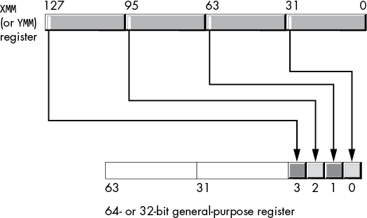
Figure 11-45: movmskps operation
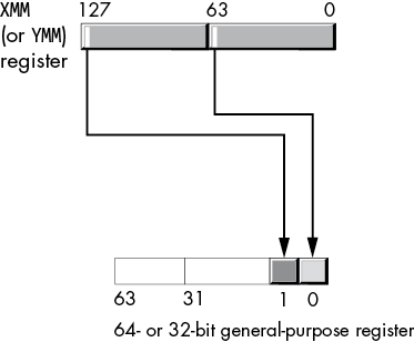
Figure 11-46: movmskpd operation
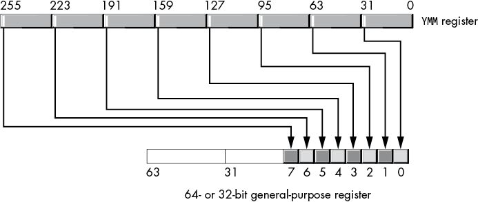
Figure 11-47: vmovmskps operation
The vmovmskpd instruction copies the sign bits from the four double-precision floating-point values in the source YMM register to bits 0 to 3 of the destination register, as shown in Figure 11-48.
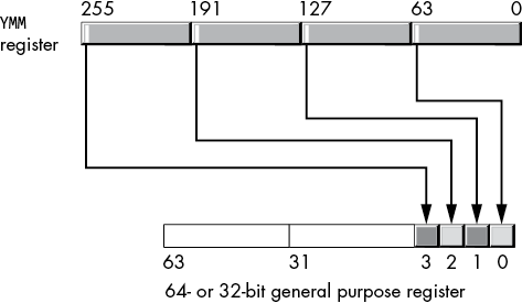
Figure 11-48: vmovmskpd operation
This instruction, with an XMM source register, will copy the sign bits from the two double-precision floating-point values into bits 0 and 1 of the destination register. In all cases, these instructions zero-extend the results into the upper bits of the general-purpose destination register. Note that these instructions do not allow memory operands.
Although the stated data type for these instructions is packed single-precision and packed double-precision, you will also use these instructions on 32-bit integers (movmskps and vmovmskps) and 64-bit integers (movmskpd and vmovmskpd). Specifically, these instructions are perfect for extracting 1-bit Boolean values from the various lanes after one of the (dword or qword) packed integer comparisons as well as after the single- or double-precision floating-point comparisons (remember that although the packed floating-point comparisons compare floating-point values, their results are actually integer values).
Consider the following instruction sequence:
         cmpeqpd  xmm0, xmm1
         movmskpd rax,  xmm0      ; Moves 2 bits into RAX
         lea      rcx,  jmpTable
         jmp      qword ptr [rcx][rax*8]

jmpTable qword    nene
         qword    neeq
         qword    eqne
         qword    eqeq
Because movmskpd extracts 2 bits from XMM0 and stores them into RAX, this code can use RAX as an index into a jump table to select four different branch labels. The code at label nene executes if both comparisons produce not equal; label neeq is the target when the lane 0 values are equal but the lane 1 values are not equal. Label eqne is the target when the lane 0 values are not equal but the lane 1 values are equal. Finally, label eqeq is where this code branches when both sets of lanes contain equal values.
11.13 Floating-Point Conversion Instructions
Previously, I described several instructions to convert data between various scalar floating-point and integer formats (see “SSE Floating-Point Conversions” in Chapter 6). Variants of these instructions also exist for packed data conversions. Table 11-31 lists many of these instructions you will commonly use.
Table 11-31: SSE Conversion Instructions
| Instruction syntax | Description |
cvtdq2pd xmmdest, xmmsrc/mem64 |
Converts two packed signed double-word integers from XMMsrc/mem64 to two packed double-precision floating-point values in XMMdest. If YMM register is present, this instruction leaves the HO bits unchanged. |
vcvtdq2pd xmmdest, xmmsrc/mem64 |
(AVX) Converts two packed signed double-word integers from XMMsrc/mem64 to two packed double-precision floating-point values in XMMdest. This instruction stores 0s into the HO bits of the underlying YMM register. |
vcvtdq2pd ymmdest, xmmsrc/mem128 |
(AVX) Converts four packed signed double-word integers from XMMsrc/mem128 to four packed double-precision floating-point values in YMMdest. |
cvtdq2ps xmmdest, xmmsrc/mem128 |
Converts four packed signed double-word integers from XMMsrc/mem128 to four packed single-precision floating-point values in XMMdest. If YMM register is present, this instruction leaves the HO bits unchanged. |
vcvtdq2ps xmmdest, xmmsrc/mem128 |
(AVX) Converts four packed signed double-word integers from XMMsrc/mem128 to four packed single-precision floating-point values in XMMdest. If YMM register is present, this instruction writes 0s to the HO bits. |
vcvtdq2ps ymmdest, ymmsrc/mem256 |
(AVX) Converts eight packed signed double-word integers from YMMsrc/mem256 to eight packed single-precision floating-point values in YMMdest. If YMM register is present, this instruction writes 0s to the HO bits. |
cvtpd2dq xmmdest, xmmsrc/mem128 |
Converts two packed double-precision floating-point values from XMMsrc/mem128 to two packed signed double-word integers in XMMdest. If YMM register is present, this instruction leaves the HO bits unchanged. The conversion from floating-point to integer uses the current SSE rounding mode. |
vcvtpd2dq xmmdest, xmmsrc/mem128 |
(AVX) Converts two packed double-precision floating-point values from XMMsrc/mem128 to two packed signed double-word integers in XMMdest. This instruction stores 0s into the HO bits of the underlying YMM register. The conversion from floating-point to integer uses the current AVX rounding mode. |
vcvtpd2dq xmmdest, ymmsrc/mem256 |
(AVX) Converts four packed double-precision floating-point values from YMMsrc/mem256 to four packed signed double-word integers in XMMdest. The conversion of floating-point to integer uses the current AVX rounding mode. |
cvtpd2ps xmmdest, xmmsrc/mem128 |
Converts two packed double-precision floating-point values from XMMsrc/mem128 to two packed single-precision floating-point values in XMMdest. If YMM register is present, this instruction leaves the HO bits unchanged. |
vcvtpd2ps xmmdest, xmmsrc/mem128 |
(AVX) Converts two packed double-precision floating-point values from XMMsrc/mem128 to two packed single-precision floating-point values in XMMdest. This instruction stores 0s into the HO bits of the underlying YMM register. |
vcvtpd2ps xmmdest, ymmsrc/mem256 |
(AVX) Converts four packed double-precision floating-point values from YMMsrc/mem256 to four packed single-precision floating-point values in YMMdest. |
cvtps2dq xmmdest, xmmsrc/mem128 |
Converts four packed single-precision floating-point values from XMMsrc/mem128 to four packed signed double-word integers in XMMdest. If YMM register is present, this instruction leaves the HO bits unchanged. The conversion of floating-point to integer uses the current SSE rounding mode. |
vcvtps2dq xmmdest, xmmsrc/mem128 |
(AVX) Converts four packed single-precision floating-point values from XMMsrc/mem128 to four packed signed double-word integers in XMMdest. This instruction stores 0s into the HO bits of the underlying YMM register. The conversion of floating-point to integer uses the current AVX rounding mode. |
vcvtps2dq ymmdest, ymmsrc/mem256 |
(AVX) Converts eight packed single-precision floating-point values from YMMsrc/mem256 to eight packed signed double-word integers in YMMdest. The conversion of floating-point to integer uses the current AVX rounding mode. |
cvtps2pd xmmdest, xmmsrc/mem64 |
Converts two packed single-precision floating-point values from XMMsrc/mem64 to two packed double-precision values in XMMdest. If YMM register is present, this instruction leaves the HO bits unchanged. |
vcvtps2pd xmmdest, xmmsrc/mem64 |
(AVX) Converts two packed single-precision floating-point values from XMMsrc/mem64 to two packed double-precision values in XMMdest. This instruction stores 0s into the HO bits of the underlying YMM register. |
vcvtps2pd ymmdest, xmmsrc/mem128 |
(AVX) Converts four packed single-precision floating-point values from XMMsrc/mem128 to four packed double-precision values in YMMdest. |
cvttpd2dq xmmdest, xmmsrc/mem128 |
Converts two packed double-precision floating-point values from XMMsrc/mem128 to two packed signed double-word integers in XMMdest using truncation. If YMM register is present, this instruction leaves the HO bits unchanged. |
vcvttpd2dq xmmdest, xmmsrc/mem128 |
(AVX) Converts two packed double-precision floating-point values from XMMsrc/mem128 to two packed signed double-word integers in XMMdest using truncation. This instruction stores 0s into the HO bits of the underlying YMM register. |
vcvttpd2dq xmmdest, ymmsrc/mem256 |
(AVX) Converts four packed double-precision floating-point values from YMMsrc/mem256 to four packed signed double-word integers in XMMdest using truncation. |
cvttps2dq xmmdest, xmmsrc/mem128 |
Converts four packed single-precision floating-point values from XMMsrc/mem128 to four packed signed double-word integers in XMMdest using truncation. If YMM register is present, this instruction leaves the HO bits unchanged. |
vcvttps2dq xmmdest, xmmsrc/mem128 |
(AVX) Converts four packed single-precision floating-point values from XMMsrc/mem128 to four packed signed double-word integers in XMMdest using truncation. This instruction stores 0s into the HO bits of the underlying YMM register. |
vcvttps2dq ymmdest, ymmsrc/mem256 |
(AVX) Converts eight packed single-precision floating-point values from YMMsrc/mem256 to eight packed signed double-word integers in YMMdest using truncation. |
11.14 Aligning SIMD Memory Accesses
Most SSE and AVX instructions require their memory operands to be on a 16-byte (SSE) or 32-byte (AVX) boundary, but this is not always possible. The easiest way to handle unaligned memory addresses is to use instructions that don’t require aligned memory operands, like movdqu, movups, and movupd. However, the performance hit of using unaligned data movement instructions often defeats the purpose of using SSE/AVX instructions in the first place.
Instead, the trick to aligning data for use by SIMD instructions is to process the first few data items by using standard general-purpose registers until you reach an address that is aligned properly. For example, suppose you want to use the pcmpeqb instruction to compare blocks of 16 bytes in a large array of bytes. pcmpeqb requires its memory operands to be at 16-byte-aligned addresses, so if the memory operand is not already 16-byte-aligned, you can process the first 1 to 15 bytes in the array by using standard (non-SSE) instructions until you reach an appropriate address for pcmpeqb; for example:
cmpLp:  mov  al, [rsi]
        cmp  al, someByteValue
        je   foundByte
        inc  rsi
        test rsi, 0Fh
        jnz  cmpLp
 Use SSE instructions here, as RSI is now 16-byte-aligned
ANDing RSI with 0Fh produces a 0 result (and sets the zero flag) if the LO 4 bits of RSI contain 0. If the LO 4 bits of RSI contain 0, the address it contains is aligned on a 16-byte boundary.16
The only drawback to this approach is that you must process as many as 15 bytes individually until you get an appropriate address. That’s 6 × 15, or 90, machine instructions. However, for large blocks of data (say, more than about 48 or 64 bytes), you amortize the cost of the single-byte comparisons, and this approach isn’t so bad.
To improve the performance of this code, you can modify the initial address so that it begins at a 16-byte boundary. ANDing the value in RSI (in this particular example) with 0FFFFFFFFFFFFFFF0h (–16) modifies RSI so that it holds the address of the start of the 16-byte block containing the original address:17
and rsi, -16To avoid matching unintended bytes before the start of the data structure, we can create a mask to cover the extra bytes. For example, suppose that we’re using the following instruction sequence to rapidly compare 16 bytes at a time:
           sub      rsi, 16
cmpLp:     add      rsi, 16
           movdqa   xmm0, xmm2   ; XMM2 contains bytes to test
           pcmpeqb  xmm0, [rsi]
           pmovmskb eax, xmm0
           ptest    eax, eax
           jz       cmpLp
If we use the AND instruction to align the RSI register prior to the execution of this code, we might get false results when we compare the first 16 bytes. To solve this, we can create a mask that will eliminate any bits from unintended comparisons. To create this mask, we start with all 1 bits and zero out any bits corresponding to addresses from the beginning of the 16-byte block to the first actual data item we’re comparing. This mask can be calculated using the following expression:
-1 << (startAdrs & 0xF) ; Note: -1 is all 1 bitsThis creates 0 bits in the locations before the data to compare and 1 bit thereafter (for the first 16 bytes). We can use this mask to zero out the undesired bit results from the pmovmskb instruction. The following code snippet demonstrates this technique:
           mov    rcx, rsi
           and    rsi, -16   ; Align to 16 bits
           and    ecx, 0fH   ; Strip out offset of start of data
           mov    ebx, -1    ; 0FFFFFFFFh – all 1 bits
           shl    ebx, cl    ; Create mask

; Special case for the first 1 to 16 bytes:

           movdqa   xmm0, xmm2
           pcmpeqb  xmm0, [rsi]
           pmovmskb eax, xmm0
           and      eax, ebx
           jnz      foundByte
cmpLp:     add      rsi, 16
           movdqa   xmm0, xmm2   ; XMM2 contains bytes to test
           pcmpeqb  xmm0, [rsi]
           pmovmskb eax, xmm0
           test     eax, eax
           jz       cmpLp
foundByte:
 Do whatever needs to be done when the block of 16 bytes
   contains at least one match between the bytes in XMM2
   and the data at RSI
Suppose, for example, that the address is already aligned on a 16-byte boundary. ANDing that value with 0Fh produces 0. Shifting –1 to the left zero positions produces –1 (all 1 bits). Later, when the code logically ANDs this with the mask obtained after the pcmpeqb and pmovmskb instructions, the result does not change. Therefore, the code tests all 16 bytes (as we would want if the original address is 16-byte-aligned).
When the address in RSI has the value 0001b in the LO 4 bits, the actual data starts at offset 1 into the 16-byte block. So, we want to ignore the first byte when comparing the values in XMM2 against the 16 bytes at [RSI]. In this case, the mask is 0FFFFFFFEh, which is all 1s except for a 0 in bit 0. After the comparison, if bit 0 of EAX contains a 1 (meaning the bytes at offset 0 match), the AND operation eliminates this bit (replacing it with 0) so it doesn’t affect the comparison. Likewise, if the starting offset into the block is 2, 3, . . . , 15, the shl instruction modifies the bit mask in EBX to eliminate bytes at those offsets from consideration in the first compare operation. The result is that it takes only 11 instructions to do the same work as (up to) 90+ instructions in the original (byte-by-byte comparison) example.
11.15 Aligning Word, Dword, and Qword Object Addresses
When aligning non-byte-sized objects, you increment the pointer by the size of the object (in bytes) until you obtain an address that is 16- (or 32-) byte-aligned. However, this works only if the object size is 2, 4, or 8 (because any other value will likely miss addresses that are multiples of 16).
For example, you can process the first several elements of an array of word objects (where the first element of the array appears at an even address in memory) on a word-by-word basis, incrementing the pointer by 2, until you obtain an address that is divisible by 16 (or 32). Note, though, that this scheme works only if the array of objects begins at an address that is a multiple of the element size. For example, if an array of word values begins at an odd address in memory, you will not be able to get an address that is divisible by 16 or 32 with a series of additions by 2, and you would not be able to use SSE/AVX instructions to process this data without first moving it to another location in memory that is properly aligned.
11.16 Filling an XMM Register with Several Copies of the Same Value
For many SIMD algorithms, you will want multiple copies of the same value in an XMM or a YMM register. You can use the (v)movddup, (v)movshdup, (v)pinsd, (v)pinsq, and (v)pshufd instructions for single-precision and double-precision floating-point values. For example, if you have a single-precision floating-point value, r4var, in memory and you want to replicate it throughout XMM0, you could use the following code:
movss  xmm0, r4var
pshufd xmm0, xmm0, 0    ; Lanes 3, 2, 1, and 0 from lane 0
To copy a pair of double-precision floating-point values from r8var into XMM0, you could use:
movsd  xmm0, r8var
pshufd xmm0, xmm0, 44h  ; Lane 0 to lanes 0 and 2, 1 to 1, and 3
Of course, pshufd is really intended for double-word integer operations, so additional latency (time) may be involved in using pshufd immediately after movsd or movss. Although pshufd allows a memory operand, that operand must be a 16-byte-aligned 128-bit-memory operand, so it’s not useful for directly copying a floating-point value through an XMM register.
For double-precision floating-point values, you can use movddup to duplicate a single 64-bit float in the LO bits of an XMM register into the HO bits:
movddup xmm0, r8varThe movddup instruction allows unaligned 64-bit memory operands, so it’s probably the best choice for duplicating double-precision values.
To copy byte, word, dword, or qword integer values throughout an XMM register, the pshufb, pshufw, pshufd, or pshufq instructions are a good choice. For example, to replicate a single byte throughout XMM0, you could use the following sequence:
movzx  eax, byteToCopy
movd   xmm0, eax
pxor   xmm1, xmm1   ; Mask to copy byte 0 throughout
pshufb xmm0, xmm1
The XMM1 operand is an array of bytes containing masks used to copy data from locations in XMM0 onto itself. The value 0 copies byte 0 in XMM0 throughout all the other bits in XMM0. This same code can be used to copy words, dwords, and qwords by simply changing the mask value in XMM1. Or you could use the pshuflw or pshufd instructions to do the job. Here’s another variant that replicates a byte throughout XMM0:
movzx     eax, byteToCopy
mov       ah, al
movd      xmm0, eax
punpcklbw xmm0, xmm0    ; Copy bytes 0 and 1 to 2 and 3
pshufd    xmm0, xmm0, 0 ; Copy LO dword throughout
11.17 Loading Some Common Constants Into XMM and YMM Registers
No SSE/AVX instructions let you load an immediate constant into a register. However, you can use a couple of idioms (tricks) to load certain common constant values into an XMM or a YMM register. This section discusses some of these idioms.
Loading 0 into an SSE/AVX register uses the same idiom that general-purpose integer registers employ: exclusive-OR the register with itself. For example, to set all the bits in XMM0 to 0s, you would use the following instruction:
pxor xmm0, xmm0To set all the bits in an XMM or a YMM register to 1, you can use the pcmpeqb instruction, as follows:
pcmpeqb xmm0, xmm0Because any given XMM or YMM register is equal to itself, this instruction stores 0FFh in all the bytes of XMM0 (or whatever XMM or YMM register you specify).
If you want to load the 8-bit value 01h into all 16 bytes of an XMM register, you can use the following code (this comes from Intel):
pxor    xmm0, xmm0
pcmpeqb xmm1, xmm1
psubb   xmm0, xmm1   ; 0 - (-1) is (1)
You can substitute psubw or psubd for psubb in this example if you want to create 16- or 32-bit results (for example, four 32-bit dwords in XMM0, each containing the value 00000001h).
If you would like the 1 bit in a different bit position (rather than bit 0 of each byte), you can use the pslld instruction after the preceding sequence to reposition the bits. For example, if you want to load the XMM0 register with 8080808080808080h, you could use the following instruction sequence:
pxor    xmm0, xmm0
pcmpeqb xmm1, xmm1
psubb   xmm0, xmm1
pslld   xmm0, 7         ; 01h -> 80h in each byte
Of course, you can supply a different immediate constant to pslld to load each byte in the register with 02h, 04h, 08h, 10h, 20h, or 40h.
Here’s a neat trick you can use to load 2n – 1 (all 1 bits up to the nth bit in a number) into all the lanes on an SSE/AVX register:18
; For 16-bit lanes:

pcmpeqd  xmm0, xmm0     ; Set all bits to 1
psrlw    xmm0, 16 - n   ; Clear top 16 - n bits of xmm0

; For 32-bit lanes:

pcmpeqd  xmm0, xmm0     ; Set all bits to 1
psrld    xmm0, 32 - n   ; Clear top 16 - n bits of xmm0

; For 64-bit lanes:

pcmpeqd  xmm0, xmm0     ; Set all bits to 1
psrlq    xmm0, 64 - n   ; Clear top 16 - n bits of xmm0
You can also load the inverse (NOT(2n – 1), all 1 bits in bit position n through the end of the register) by shifting to the left rather than the right:
; For 16-bit lanes:

pcmpeqd  xmm0, xmm0     ; Set all bits to 1
psllw    xmm0, n        ; Clear bottom n bits of xmm0

; For 32-bit lanes:

pcmpeqd  xmm0, xmm0     ; Set all bits to 1
pslld    xmm0, n        ; Clear bottom n bits of xmm0

; For 64-bit lanes:

pcmpeqd  xmm0, xmm0     ; Set all bits to 1
psllq    xmm0, n        ; Clear bottom n bits of xmm0
Of course, you can also load a “constant” into an XMM or a YMM register by putting that constant into a memory location (preferably 16- or 32-byte-aligned) and then using a movdqu or movdqa instruction to load that value into a register. Do keep in mind, however, that such an operation can be relatively slow if the data in memory does not appear in cache. Another possibility, if the constant is small enough, is to load the constant into a 32- or 64-bit integer register and use movd or movq to copy that value into an XMM register.
11.18 Setting, Clearing, Inverting, and Testing a Single Bit in an SSE Register
Here’s another set of tricks suggested by Raymond Chen (https://blogs.msdn.microsoft.com/oldnewthing/20141222-00/?p=43333/) to set, clear, or test an individual bit in an XMM register.
To set an individual bit (bit n, assuming that n is a constant) with all other bits cleared, you can use the following macro:
; setXBit - Sets bit n in SSE register xReg.

setXBit  macro   xReg, n
         pcmpeqb xReg, xReg   ; Set all bits in xReg
         psrlq   xReg, 63     ; Set both 64-bit lanes to 01h
         if      n lt 64
         psrldq  xReg, 8      ; Clear the upper lane
         else
         pslldq  xReg, 8      ; Clear the lower lane
         endif
         if      (n and 3fh) ne 0
         psllq   xReg, (n and 3fh)
         endif
         endm
Once you can fill an XMM register with a single set bit, you can use that register’s value to set, clear, invert, or test that bit in another XMM register. For example, to set bit n in XMM1, without affecting any of the other bits in XMM1, you could use the following code sequence:
setXBit xmm0, n      ; Set bit n in XMM1 to 1 without
por     xmm1, xmm0   ; affecting any other bits
To clear bit n in an XMM register, you use the same sequence but substitute the vpandn (AND NOT) instruction for the por instruction:
setXBit xmm0, n            ; Clear bit n in XMM1 without
vpandn  xmm1, xmm0, xmm1   ; affecting any other bits
To invert a bit, simply substitute pxor for por or vpandn:
setXBit xmm0, n      ; Invert bit n in XMM1 without
pxor    xmm1, xmm0   ; affecting any other bits
To test a bit to see if it is set, you have a couple of options. If your CPU supports the SSE4.1 instruction set extensions, you can use the ptest instruction:
setXBit xmm0, n      ; Test bit n in XMM1
ptest   xmm1, xmm0
jnz     bitNisSet    ; Fall through if bit n is clear
If you have an older CPU that doesn’t support the ptest instruction, you can use pmovmskb as follows:
; Remember, psllq shifts bits, not bytes.
; If bit n is not in bit position 7 of a given
; byte, then move it there. For example, if n = 0, then
; (7 - (0 and 7)) is 7, so psllq moves bit 0 to bit 7.

movdqa   xmm0, xmm1
if       7 - (n and 7)
psllq    xmm0, 7 - (n and 7)
endif

; Now that the desired bit to test is sitting in bit position
; 7 of *some* byte, use pmovmskb to extract all bit 7s into AX:

pmovmskb eax, xmm0

; Now use the (integer) test instruction to test that bit:

test    ax, 1 shl (n / 8)
jnz     bitNisSet
11.19 Processing Two Vectors by Using a Single Incremented Index
Sometimes your code will need to process two blocks of data simultaneously, incrementing pointers into both blocks during the execution of the loop.
One easy way to do this is to use the scaled-indexed addressing mode. If R8 and R9 contain pointers to the data you want to process, you can walk along both blocks of data by using code such as the following:
          dec rcx
blkLoop:  inc rcx
          mov eax, [r8][rcx * 4]
          cmp eax, [r9][rcx * 4]
          je  theyreEqual
          cmp eax, sentinelValue
          jne blkLoop
This code marches along through the two dword arrays comparing values (to search for an equal value in the arrays at the same index). This loop uses four registers: EAX to compare the two values from the arrays, the two pointers to the arrays (R8 and R9), and then the RCX index register to step through the two arrays.
It is possible to eliminate RCX from this loop by incrementing the R8 and R9 registers in this loop (assuming it’s okay to modify the values in R8 and R9):
          sub r8, 4
          sub r9, 4
blkLoop:  add r8, 4
          add r9, 4
          mov eax, [r8]
          cmp eax, [r9]
          je  theyreEqual
          cmp eax, sentinelValue
          jne blkLoop
This scheme requires an extra add instruction in the loop. If the execution speed of this loop is critical, inserting this extra addition could be a deal breaker.
There is, however, a sneaky trick you can use so that you have to increment only a single register on each iteration of the loop:
          sub r9, r8            ; R9 = R9 - R8
          sub r8, 4
blkLoop:  add r8, 4
          mov eax, [r8]
          cmp eax, [r9][r8 * 1] ; Address = R9 + R8
          je  theyreEqual
          cmp eax, sentinelValue
          jne blkLoop
The comments are there because they explain the trick being used. At the beginning of the code, you subtract the value of R8 from R9 and leave the result in R9. In the body of the loop, you compensate for this subtraction by using the [r9][r8 * 1] scaled-indexed addressing mode (whose effective address is the sum of R8 and R9, thus restoring R9 to its original value, at least on the first iteration of the loop). Now, because the cmp instruction’s memory address is the sum of R8 and R9, adding 4 to R8 also adds 4 to the effective address used by the cmp instruction. Therefore, on each iteration of the loop, the mov and cmp instructions look at successive elements of their respective arrays, yet the code has to increment only a single pointer.
This scheme works especially well when processing SIMD arrays with SSE and AVX instructions because the XMM and YMM registers are 16 and 32 bytes each, so you can’t use normal scaling factors (1, 2, 4, or 8) to index into an array of packed data values. You wind up having to add 16 (or 32) to your pointers when stepping through the arrays, thus losing one of the benefits of the scaled-indexed addressing mode. For example:
; Assume R9 and R8 point at (32-byte-aligned) arrays of 20 double values.
; Assume R10 points at a (32-byte-aligned) destination array of 20 doubles.

          sub     r9, r8     ; R9 = R9 - R8
          sub     r10, r8    ; R10 = R10 – R8
          sub     r8, 32
          mov     ecx, 5     ; Vector with 20 (5 * 4) double values
addLoop:  add     r8, 32
          vmovapd ymm0, [r8]
          vaddpd  ymm0, ymm0, [r9][r8 * 1] ; Address = R9 + R8
          vmovapd [r10][r8 * 1], ymm0      ; Address = R10 + R8
          dec     ecx
          jnz     addLoop
11.20 Aligning Two Addresses to a Boundary
The vmovapd and vaddpd instructions from the preceding example require their memory operands to be 32-byte-aligned or you will get a general protection fault (memory access violation). If you have control over the placement of the arrays in memory, you can specify an alignment for the arrays. If you have no control over the data’s placement in memory, you have two options: working with the unaligned data regardless of the performance loss, or moving the data to a location where it is properly aligned.
If you must work with unaligned data, you can substitute an unaligned move for an aligned move (for example, vmovupd for vmovdqa) or load the data into a YMM register by using an unaligned move and then operate on the data in that register by using your desired instruction. For example:
addLoop:  add     r8, 32
          vmovupd ymm0, [r8]
          vmovupd ymm1, [r9][r8 * 1]  ; Address = R9 + R8
          vaddpd  ymm0, ymm0, ymm1
          vmovupd [r10][r8 * 1], ymm0 ; Address = R10 + R8
          dec     ecx
          jnz     addLoop
Sadly, the vaddpd instruction does not support unaligned access to memory, so you must load the value from the second array (pointed at by R9) into another register (YMM1) before the packed addition operation. This is the drawback to unaligned access: not only are unaligned moves slower, but you also may need to use additional registers and instructions to deal with unaligned data.
Moving the data to a memory location whose alignment you can control is an option when you have a data operand you will be using over and over again in the future. Moving data is an expensive operation; however, if you have a standard block of data you’re going to compare against many other blocks, you can amortize the cost of moving that block to a new location over all the operations you need to do.
Moving the data is especially useful when one (or both) of the data arrays appears at an address that is not an integral multiple of the sub-elements’s size. For example, if you have an array of dwords that begin at an odd address, you will never be able to align a pointer to that array’s data to a 16-byte boundary without moving the data.
11.21 Working with Blocks of Data Whose Length Is Not a Multiple of the SSE/AVX Register Size
Using SIMD instructions to march through a large data set processing 2, 4, 8, 16, or 32 values at a time often allows a SIMD algorithm (a vectorized algorithm) to run an order of magnitude faster than the SISD (scalar) algorithm. However, two boundary conditions create problems: the start of the data set (when the starting address might not be properly aligned) and the end of the data set (when there might not be a sufficient number of array elements to completely fill an XMM or a YMM register). I’ve addressed the issues with the start of the data set (misaligned data) already. This section takes a look at the latter problem.
For the most part, when you run out of data at the end of the array (and the XMM and YMM registers need more for a packed operation), you can use the same technique given earlier for aligning a pointer: load more data than is necessary into the register and mask out the unneeded results. For example, if only 8 bytes are left to process in a byte array, you can load 16 bytes, do the operation, and ignore the results from the last 8 bytes. In the comparison loop examples I’ve been using through these past sections, you could do the following:
movdqa   xmm0, [r8]
pcmpeqd  xmm0, [r9]
pmovmskb eax, xmm0
and      eax, 0ffh     ; Mask out the last 8 compares
cmp      eax, 0ffh
je       matchedData
In most cases, accessing data beyond the end of the data structures (either the data pointed at by R8, R9, or both in this example) is harmless. However, as you saw in “Memory Access and 4K Memory Management Unit Pages” in Chapter 3, if that extra data happens to cross a memory management unit page, and that new page doesn’t allow read access, the CPU will generate a general protection fault (memory access or segmentation fault). Therefore, unless you know that valid data follows the array in memory (at least to the extent the instruction references), you shouldn’t access that memory area; doing so could crash your software.
This problem has two solutions. First, you can align memory accesses on an address boundary that is the same size as the register (for example, 16-byte alignment for XMM registers). Accessing data beyond the end of the data structure with an SSE/AVX instruction will not cross a page boundary (because 16-byte accesses aligned on 16-byte boundaries will always fall within the same MMU page, and ditto for 32-byte accesses on 32-byte boundaries).
The second solution is to examine the memory address prior to accessing memory. While you cannot access the new page without possibly triggering an access fault,19 you can check the address itself and see if accessing 16 (or 32) bytes at that address will access data in a new page. If it would, you can take some precautions before accessing the data on the next page. For example, rather than continuing to process the data in SIMD mode, you could drop down to SISD mode and finish processing the data to the end of the array by using standard scalar instructions.
To test if a SIMD access will cross an MMU page boundary, supposing that R9 contains the address at which you’re about to access 16 bytes in memory using an SSE instruction, use code like the following:
mov  eax, r9d
and  eax, 0fffh
cmp  eax, 0ff0h
ja   willCrossPage
Each MMU page is 4KB long and is situated on a 4KB address boundary in memory. Therefore, the LO 12 bits of an address provide an index into the MMU page associated with that address. The preceding code checks whether the address has a page offset greater than 0FF0h (4080). If so, then accessing 16 bytes starting at that address will cross a page boundary. Check for a value of 0FE0h if you need to check for a 32-byte access.
11.22 Dynamically Testing for a CPU Feature
At the beginning of this chapter, I mentioned that when testing the CPU feature set to determine which extensions it supports, the best solution is to dynamically select a set of functions based on the presence or absence of certain capabilities. To demonstrate dynamically testing for, and using (or avoiding), certain CPU features—specifically, testing for the presence of AVX extensions—I’ll modify (and expand) the print procedure that I’ve been using in examples up to this point.
The print procedure I’ve been using is very convenient, but it doesn’t preserve any SSE or AVX registers that a call to printf() could (legally) modify. A generic version of print should preserve the volatile XMM and YMM registers as well as general-purpose registers.
The problem is that you cannot write a generic version of print that will run on all CPUs. If you preserve the XMM registers only, the code will run on any x86-64 CPU. However, if the CPU supports the AVX extensions and the program uses YMM0 to YMM5, the print routine will preserve only the LO 128 bits of those registers, as they are aliased to the corresponding XMM registers. If you save the volatile YMM registers, that code will crash on a CPU that doesn’t support the AVX extensions. So, the trick is to write code that will dynamically determine whether the CPU has the AVX registers and preserve them if they are present, and otherwise preserve only the SSE registers.
The easy way to do this, and probably the most appropriate solution for the print function, is to simply stick the cpuid instruction inside print and test the results immediately before preserving (and restoring) the registers. Here’s a code fragment that demonstrates how this could be done:
AVXSupport  =     10000000h              ; Bit 28

print       proc

; Preserve all the volatile registers
; (be nice to the assembly code that
; calls this procedure):

            push    rax
            push    rbx                  ; CPUID messes with EBX
            push    rcx
            push    rdx
            push    r8
            push    r9
            push    r10
            push    r11

; Reserve space on the stack for the AVX/SSE registers.
; Note: SSE registers need only 96 bytes, but the code
; is easier to deal with if we reserve the full 128 bytes
; that the AVX registers need and ignore the extra 64
; bytes when running SSE code.

            sub     rsp, 192

; Determine if we have to preserve the YMM registers:

            mov     eax, 1
            cpuid
            test    ecx, AVXSupport      ; Test bits 19 and 20
            jnz     preserveAVX

; No AVX support, so just preserve the XXM0 to XXM3 registers:

            movdqu  xmmword ptr [rsp + 00], xmm0
            movdqu  xmmword ptr [rsp + 16], xmm1
            movdqu  xmmword ptr [rsp + 32], xmm2
            movdqu  xmmword ptr [rsp + 48], xmm3
            movdqu  xmmword ptr [rsp + 64], xmm4
            movdqu  xmmword ptr [rsp + 80], xmm5
            jmp     restOfPrint

; YMM0 to YMM3 are considered volatile, so preserve them:

preserveAVX:
            vmovdqu ymmword ptr [rsp + 000], ymm0
            vmovdqu ymmword ptr [rsp + 032], ymm1
            vmovdqu ymmword ptr [rsp + 064], ymm2
            vmovdqu ymmword ptr [rsp + 096], ymm3
            vmovdqu ymmword ptr [rsp + 128], ymm4
            vmovdqu ymmword ptr [rsp + 160], ymm5

restOfPrint:
        The rest of the print function goes here
At the end of the print function, when it’s time to restore everything, you could do another test to determine whether to restore XMM or YMM registers.20
For other functions, when you might not want the expense of cpuid (and preserving all the registers it stomps on) incurred on every function call, the trick is to write three functions: one for SSE CPUs, one for AVX CPUs, and a special function (that you call only once) that selects which of these two you will call in the future. The bit of magic that makes this efficient is indirection. You won’t directly call any of these functions. Instead, you’ll initialize a pointer with the address of the function to call and indirectly call one of these three functions by using the pointer. For the current example, we’ll name this pointer print and initialize it with the address of the third function, choosePrint:
          .data
print     qword   choosePrint
Here’s the code for choosePrint:
; On first call, determine if we support AVX instructions
; and set the "print" pointer to point at print_AVX or
; print_SSE:

choosePrint proc
            push    rax             ; Preserve registers that get
            push    rbx             ; tweaked by CPUID
            push    rcx
            push    rdx

            mov     eax, 1
            cpuid
            test    ecx, AVXSupport ; Test bit 28 for AVX
            jnz     doAVXPrint

            lea     rax, print_SSE  ; From now on, call
            mov     print, rax      ; print_SSE directly

; Return address must point at the format string
; following the call to this function! So we have
; to clean up the stack and JMP to print_SSE.

            pop     rdx
            pop     rcx
            pop     rbx
            pop     rax
            jmp     print_SSE

doAVXPrint: lea     rax, print_AVX  ; From now on, call
            mov     print, rax      ; print_AVX directly

; Return address must point at the format string
; following the call to this function! So we have
; to clean up the stack and JMP to print_AUX.

            pop     rdx
            pop     rcx
            pop     rbx
            pop     rax
            jmp     print_AVX

choosePrint endp
The print_SSE procedure runs on CPUs without AVX support, and the print_AVX procedure runs on CPUs with AVX support. The choosePrint procedure executes the cpuid instruction to determine whether the CPU supports the AVX extensions; if so, it initializes the print pointer with the address of the print_AVX procedure, and if not, it stores the address of print_SSE into the print variable.
choosePrint is not an explicit initialization procedure you must call prior to calling print. The choosePrint procedure executes only once (assuming you call it via the print pointer rather than calling it directly). After the first execution, the print pointer contains the address of the CPU-appropriate print function, and choosePrint no longer executes.
You call the print pointer just as you would make any other call to print; for example:
call print
byte "Hello, world!", nl, 0
After setting up the print pointer, choosePrint must transfer control to the appropriate print procedure (print_SSE or print_AVX) to do the work the user is expecting. Because preserved register values are sitting on the stack, and the actual print routines expect only a return address, choosePrint will first restore all the (general-purpose) registers it saved and then jump to (not call) the appropriate print procedure. It does a jump, rather than a call, because the return address pointing to the format string is already sitting on the top of the stack. On return from the print_SSE or print_AVX procedure, control will return to whomever called choosePrint (via the print pointer).
Listing 11-5 shows the complete print function, with print_SSE and print_AVX, and a simple main program that calls print. I’ve extended print to accept arguments in R10 and R11 as well as in RDX, R8, and R9 (this function reserves RCX to hold the address of the format string following the call to print).
; Listing 11-5

; Generic print procedure and dynamically
; selecting CPU features.

        option  casemap:none

nl          =       10

; SSE4.2 feature flags (in ECX):

SSE42       =       00180000h       ; Bits 19 and 20
AVXSupport  =       10000000h       ; Bit 28

; CPUID bits (EAX = 7, EBX register)

AVX2Support  =      20h             ; Bit 5 = AVX

            .const
ttlStr      byte    "Listing 11-5", 0

            .data
            align   qword
print       qword   choosePrint     ; Pointer to print function

; Floating-point values for testing purposes:

fp1         real8   1.0
fp2         real8   2.0
fp3         real8   3.0
fp4         real8   4.0
fp5         real8   5.0

            .code
            externdef printf:proc

; Return program title to C++ program:

            public  getTitle
getTitle    proc
            lea     rax, ttlStr
            ret
getTitle    endp

***************************************************************

; print - "Quick" form of printf that allows the format string to
;         follow the call in the code stream. Supports up to five
;         additional parameters in RDX, R8, R9, R10, and R11.

; This function saves all the Microsoft ABI–volatile,
; parameter, and return result registers so that code
; can call it without worrying about any registers being
; modified (this code assumes that Windows ABI treats
; YMM4 to YMM15 as nonvolatile).

; Of course, this code assumes that AVX instructions are
; available on the CPU.

; Allows up to 5 arguments in:

;  RDX - Arg #1
;  R8  - Arg #2
;  R9  - Arg #3
;  R10 - Arg #4
;  R11 - Arg #5

; Note that you must pass floating-point values in
; these registers, as well. The printf function
; expects real values in the integer registers.

; There are two versions of this function, one that
; will run on CPUs without AVX capabilities (no YMM
; registers) and one that will run on CPUs that
; have AVX capabilities (YMM registers). The difference
; between the two is which registers they preserve
; (print_SSE preserves only XMM registers and will
; run properly on CPUs that don't have YMM register
; support; print_AVX will preserve the volatile YMM
; registers on CPUs with AVX support).

; On first call, determine if we support AVX instructions
; and set the "print" pointer to point at print_AVX or
; print_SSE:

choosePrint proc
            push    rax             ; Preserve registers that get
            push    rbx             ; tweaked by CPUID
            push    rcx
            push    rdx

            mov     eax, 1
            cpuid
            test    ecx, AVXSupport ; Test bit 28 for AVX
            jnz     doAVXPrint

            lea     rax, print_SSE  ; From now on, call
            mov     print, rax      ; print_SSE directly

; Return address must point at the format string
; following the call to this function! So we have
; to clean up the stack and JMP to print_SSE.

            pop     rdx
            pop     rcx
            pop     rbx
            pop     rax
            jmp     print_SSE

doAVXPrint: lea     rax, print_AVX  ; From now on, call
            mov     print, rax      ; print_AVX directly

; Return address must point at the format string
; following the call to this function! So we have
; to clean up the stack and JMP to print_AUX.

            pop     rdx
            pop     rcx
            pop     rbx
            pop     rax
            jmp     print_AVX

choosePrint endp

; Version of print that will preserve volatile
; AVX registers (YMM0 to YMM3):

print_AVX   proc

; Preserve all the volatile registers
; (be nice to the assembly code that
; calls this procedure):

            push    rax
            push    rbx
            push    rcx
            push    rdx
            push    r8
            push    r9
            push    r10
            push    r11

; YMM0 to YMM7 are considered volatile, so preserve them:

            sub     rsp, 256
            vmovdqu ymmword ptr [rsp + 000], ymm0
            vmovdqu ymmword ptr [rsp + 032], ymm1
            vmovdqu ymmword ptr [rsp + 064], ymm2
            vmovdqu ymmword ptr [rsp + 096], ymm3
            vmovdqu ymmword ptr [rsp + 128], ymm4
            vmovdqu ymmword ptr [rsp + 160], ymm5
            vmovdqu ymmword ptr [rsp + 192], ymm6
            vmovdqu ymmword ptr [rsp + 224], ymm7

            push    rbp

returnAdrs  textequ <[rbp + 328]>

            mov     rbp, rsp
            sub     rsp, 128
            and     rsp, -16

; Format string (passed in RCX) is sitting at
; the location pointed at by the return address,
; load that into RCX:

            mov     rcx, returnAdrs

; To handle more than 3 arguments (4 counting
; RCX), you must pass data on stack. However, to the
; print caller, the stack is unavailable, so use
; R10 and R11 as extra parameters (could be just
; junk in these registers, but pass them just
; in case):

            mov     [rsp + 32], r10
            mov     [rsp + 40], r11
            call    printf

; Need to modify the return address so
; that it points beyond the zero-terminating byte.
; Could use a fast strlen function for this, but
; printf is so slow it won't really save us anything.

            mov     rcx, returnAdrs
            dec     rcx
skipTo0:    inc     rcx
            cmp     byte ptr [rcx], 0
            jne     skipTo0
            inc     rcx
            mov     returnAdrs, rcx

            leave
            vmovdqu ymm0, ymmword ptr [rsp + 000]
            vmovdqu ymm1, ymmword ptr [rsp + 032]
            vmovdqu ymm2, ymmword ptr [rsp + 064]
            vmovdqu ymm3, ymmword ptr [rsp + 096]
            vmovdqu ymm4, ymmword ptr [rsp + 128]
            vmovdqu ymm5, ymmword ptr [rsp + 160]
            vmovdqu ymm6, ymmword ptr [rsp + 192]
            vmovdqu ymm7, ymmword ptr [rsp + 224]
            add     rsp, 256
            pop     r11
            pop     r10
            pop     r9
            pop     r8
            pop     rdx
            pop     rcx
            pop     rbx
            pop     rax
            ret
print_AVX   endp

; Version that will run on CPUs without
; AVX support and will preserve the
; volatile SSE registers (XMM0 to XMM3):

print_SSE   proc

; Preserve all the volatile registers
; (be nice to the assembly code that
; calls this procedure):

            push    rax
            push    rbx
            push    rcx
            push    rdx
            push    r8
            push    r9
            push    r10
            push    r11

; XMM0 to XMM3 are considered volatile, so preserve them:

            sub     rsp, 128
            movdqu  xmmword ptr [rsp + 00],  xmm0
            movdqu  xmmword ptr [rsp + 16],  xmm1
            movdqu  xmmword ptr [rsp + 32],  xmm2
            movdqu  xmmword ptr [rsp + 48],  xmm3
            movdqu  xmmword ptr [rsp + 64],  xmm4
            movdqu  xmmword ptr [rsp + 80],  xmm5
            movdqu  xmmword ptr [rsp + 96],  xmm6
            movdqu  xmmword ptr [rsp + 112], xmm7

            push    rbp

returnAdrs  textequ <[rbp + 200]>

            mov     rbp, rsp
            sub     rsp, 128
            and     rsp, -16

; Format string (passed in RCX) is sitting at
; the location pointed at by the return address,
; load that into RCX:

            mov     rcx, returnAdrs

; To handle more than 3 arguments (4 counting
; RCX), you must pass data on stack. However, to the
; print caller, the stack is unavailable, so use
; R10 and R11 as extra parameters (could be just
; junk in these registers, but pass them just
; in case):

            mov     [rsp + 32], r10
            mov     [rsp + 40], r11
            call    printf

; Need to modify the return address so
; that it points beyond the zero-terminating byte.
; Could use a fast strlen function for this, but
; printf is so slow it won't really save us anything.

            mov     rcx, returnAdrs
            dec     rcx
skipTo0:    inc     rcx
            cmp     byte ptr [rcx], 0
            jne     skipTo0
            inc     rcx
            mov     returnAdrs, rcx

            leave
            movdqu  xmm0, xmmword ptr [rsp + 00]
            movdqu  xmm1, xmmword ptr [rsp + 16]
            movdqu  xmm2, xmmword ptr [rsp + 32]
            movdqu  xmm3, xmmword ptr [rsp + 48]
            movdqu  xmm4, xmmword ptr [rsp + 64]
            movdqu  xmm5, xmmword ptr [rsp + 80]
            movdqu  xmm6, xmmword ptr [rsp + 96]
            movdqu  xmm7, xmmword ptr [rsp + 112]
            add     rsp, 128
            pop     r11
            pop     r10
            pop     r9
            pop     r8
            pop     rdx
            pop     rcx
            pop     rbx
            pop     rax
            ret
print_SSE   endp

***************************************************************

; Here is the "asmMain" function.

            public  asmMain
asmMain     proc
            push    rbx
            push    rsi
            push    rdi
            push    rbp
            mov     rbp, rsp
            sub     rsp, 56         ; Shadow storage

; Trivial example, no arguments:

            call    print
            byte    "Hello, world!", nl, 0

; Simple example with integer arguments:

            mov     rdx, 1          ; Argument #1 for printf
            mov     r8, 2           ; Argument #2 for printf
            mov     r9, 3           ; Argument #3 for printf
            mov     r10, 4          ; Argument #4 for printf
            mov     r11, 5          ; Argument #5 for printf
            call    print
            byte    "Arg 1=%d, Arg2=%d, Arg3=%d "
            byte    "Arg 4=%d, Arg5=%d", nl, 0

; Demonstration of floating-point operands. Note that
; args 1, 2, and 3 must be passed in RDX, R8, and R9.
; You'll have to load parameters 4 and 5 into R10 and R11.

            mov     rdx, qword ptr fp1
            mov     r8,  qword ptr fp2
            mov     r9,  qword ptr fp3
            mov     r10, qword ptr fp4
            mov     r11, qword ptr fp5
            call    print
            byte    "Arg1=%6.1f, Arg2=%6.1f, Arg3=%6.1f "
            byte    "Arg4=%6.1f, Arg5=%6.1f ", nl, 0

allDone:    leave
            pop     rdi
            pop     rsi
            pop     rbx
            ret     ; Returns to caller
asmMain     endp
            end
Listing 11-5: Dynamically selected print procedure
Here’s the build command and output for the program in Listing 11-5:
C:\>build listing11-5

C:\>echo off
 Assembling: listing11-5.asm
c.cpp

C:\>listing11-5
Calling Listing 11-5:
Hello, World!
Arg 1=1, Arg2=2, Arg3=3 Arg 4=4, Arg5=5
Arg1=   1.0, Arg2=   2.0, Arg3=   3.0 Arg4=   4.0, Arg5=   5.0
Listing 11-5 terminated
11.23 The MASM Include Directive
As you’ve seen already, including the source code for the print procedure in every sample listing in this book wastes a lot of space. Including the new version from the previous section in every listing would be impractical. In Chapter 15, I discuss include files, libraries, and other functionality you can use to break large projects into manageable pieces. In the meantime, however, it’s worthwhile to discuss the MASM include directive so this book can eliminate a lot of unnecessary code duplication in sample programs.
The MASM include directive uses the following syntax:
include source_filenamewhere source_filename is the name of a text file (generally in the same directory of the source file containing this include directive). MASM will take the source file and insert it into the assembly at the point of the include directive, exactly as though the text in that file had appeared in the source file being assembled.
For example, I have extracted all the source code associated with the new print procedure (the choosePrint, print_AVX, and print_SSE procedures, and the print qword variable), and I’ve inserted them into the print.inc source file.21 In listings that follow in this book, I’ll simply place the following directive in the code in place of the print function:
include print.incI’ve also put the getTitle procedure into its own header file (getTitle.inc) to be able to remove that common code from sample listings.
11.24 And a Whole Lot More
This chapter doesn’t even begin to describe all the various SSE, AVX, AVX2, and AVX512 instructions. As already mentioned, most of the SIMD instructions have a specific purpose (such as interleaving or deinterleaving bytes associated with video or audio information) that aren’t very useful outside their particular problem domain. Other instructions (at least, as this book was being written) are sufficiently new that they won’t execute on many CPUs in use today. If you’re interested in learning about more of the SIMD instructions, check out the information in the next section.
11.25 For More Information
For more information about the cpuid instruction on AMD CPUs, see the 2010 AMD document “CPUID Specification” (https://www.amd.com/system/files/TechDocs/25481.pdf). For Intel CPUs, check out “Intel Architecture and Processor Identification with CPUID Model and Family Numbers” (https://software.intel.com/en-us/articles/intel-architecture-and-processor-identification-with-cpuid-model-and-family-numbers/).
Microsoft’s website (particularly the Visual Studio documentation) has additional information on the MASM segment directive and x86-64 segments. A search for MASM Segment Directive on the internet, for example, brought up the page https://docs.microsoft.com/en-us/cpp/assembler/masm/segment?view=msvc-160/.
The complete discussion of all the SIMD instructions can be found in Intel’s documentation: Intel® 64 and IA-32 Architectures Software Developer’s Manual, Volume 2: Instruction Set Reference.
You can easily find this documentation online at Intel’s website; for example:
- https://software.intel.com/en-us/articles/intel-sdm/
- https://software.intel.com/content/www/us/en/develop/download/intel-64-and-ia-32-architectures-sdm-combined-volumes-1-2a-2b-2c-2d-3a-3b-3c-3d-and-4.html
AMD’s variant can be found at https://www.amd.com/system/files/TechDocs/40332.pdf.
Although this chapter has presented many of the SSE/AVX/AVX2 instructions and what they do, it has not spent much time describing how you would use these instructions in a typical program. You can easily find lots of useful high-performance algorithms that use SSE and AVX instructions on the internet. The following URLs provide some examples:
Tutorials on SIMD programming
- SSE Arithmetic, by Stefano Tommesani, https://tommesani.com/index.php/2010/04/24/sse-arithmetic/
- x86/x64 SIMD Instruction List, https://www.officedaytime.com/simd512e/
- Basics of SIMD Programming, Sony Computer Entertainment, http://ftp.cvut.cz/kernel/people/geoff/cell/ps3-linux-docs/CellProgrammingTutorial/BasicsOfSIMDProgramming.html
Sorting algorithms
- “A Novel Hybrid Quicksort Algorithm Vectorized Using AVX-512 on Intel Skylake,” by Berenger Bramas, https://arxiv.org/pdf/1704.08579.pdf
- “Register Level Sort Algorithm on Multi-Core SIMD Processors” by Tian Xiaochen et al., http://olab.is.s.u-tokyo.ac.jp/~kamil.rocki/xiaochen_rocki_IA3_SC13.pdf
- “Fast Quicksort Implementation Using AVX Instructions” by Shay Gueron and Vlad Krasnov, http://citeseerx.ist.psu.edu/viewdoc/download?doi=10.1.1.1009.7773&rep=rep1&type=pdf
Search algorithms
- “SIMD-Friendly Algorithms for Substring Searching” by Wojciech Mula, http://0x80.pl/articles/simd-strfind.html
- “Fast Multiple String Matching Using Streaming SIMD Extensions Technology” by Simone Faro and M. Oğuzhan Külekci, https://citeseerx.ist.psu.edu/viewdoc/download?doi=10.1.1.1041.3831&rep=rep1&type=pdf
- “k-Ary Search on Modern Processors” by Benjamin Schlegel et al., https://event.cwi.nl/damon2009/DaMoN09-KarySearch.pdf
11.26 Test Yourself
- How can you determine whether a particular SSE or AVX feature is available on the CPU?
- Why is it important to check the manufacturer of the CPU?
- What EAX setting do you use with
cpuidto obtain the feature flags? - What feature flag bit tells you that the CPU supports SSE4.2 instructions?
- What is the name of the default segment used by the following directives?
.code.data.data?.const
- What is the default segment alignment?
- How would you create a data segment aligned on a 64-byte boundary?
- Which instruction set extensions support the YMMx registers?
- What is a lane?
- What is the difference between a scalar instruction and a vector instruction?
- SSE memory operands (XMM) must usually be aligned on what memory boundary?
- AVX memory operands (YMM) must usually be aligned on what memory boundary?
- AVX-512 memory operands (ZMM) must usually be aligned on what memory boundary?
- What instruction would you use to move the data from a 32-bit general-purpose integer register into the LO 32 bits of an XMM and a YMM register?
- What instruction would you use to move the data from a 64-bit general-purpose integer register into the LO 64 bits of an XMM and a YMM register?
- What three instructions would you use to load 16 bytes from an aligned memory location into an XMM register?
- What three instructions would you use to load 16 bytes from an arbitrary memory address into an XMM register?
- If you want to move the HO 64 bits of an XMM register into the HO 64 bits of another XMM register without affecting the LO 64 bits of the destination, what instruction would you use?
- If you want to duplicate a double-precision value in the LO 64 bits of an XMM register in the two qwords (LO and HO) of another XMM register, what instruction would you use?
- Which instruction would you use to rearrange the bytes in an XMM register?
- Which instruction would you use to rearrange the dword lanes in an XMM register?
- Which instructions would you use to extract bytes, words, dwords, or qwords from an XMM register and move them into a general-purpose register?
- Which instructions would you use to take a byte, word, dword, or qword in a general-purpose register and insert it somewhere in an XMM register?
- What does the
andnpdinstruction do? - Which instruction would you use to shift the bytes in an XMM register one byte position to the left (8 bits)?
- Which instruction would you use to shift the bytes in an XMM register one byte position to the right (8 bits)?
- If you want to shift the two qwords in an XMM register n bit positions to the left, what instruction would you use?
- If you want to shift the two qwords in an XMM register n bit positions to the right, what instruction would you use?
- What happens in a
paddbinstruction when a sum will not fit into 8 bits? - What is the difference between a vertical addition and a horizontal addition?
- Where does the
pcmpeqbinstruction put the result of the comparison? How does it indicate the result is true? - There is no
pcmpltqinstruction. Explain how to compare lanes in a pair of XMM registers for the less-than condition. - What does the
pmovmskbinstruction do? - How many simultaneous additions are performed by the following?
addpsaddpd
- If you have a pointer to data in RAX and want to force that address to be aligned on a 16-byte boundary, what instruction would you use?
- How can you set all the bits in the XMM0 register to 0?
- How can you set all the bits in the XMM1 register to 1?
- What directive do you use to insert the content of a source file into the current source file during assembly?